Floating member used for waterborne photovoltaic power station and connection method thereof

A technology for photovoltaic power plants and floating bodies, which is applied in photovoltaic power plants, photovoltaic power generation, photovoltaic modules, etc., can solve the problems of inability to meet the development needs of photovoltaic power plants, poor heat dissipation effect of heat dissipation panels, and low heat dissipation efficiency of heat dissipation panels, so as to expand effective heat dissipation. area, improve anti-aging performance and reduce installation cost

Inactive Publication Date: 2015-12-23
SHANGHAI QIHUA WHARF ENG CO LTD
View PDF9 Cites 30 Cited by
  • Summary
  • Abstract
  • Description
  • Claims
  • Application Information

AI Technical Summary

Problems solved by technology

The above-mentioned structure of the utility model solves the problem that the inclination angle of the floating carrier cannot be adjusted, but the floating carrier of the above-mentioned structure is inconvenient to manufacture and install, and it is not conducive to the connection with the surrounding floating bodies or connecting parts
At the same time, since the floating body is a large-area hollow structure, the upper part is a non-metallic frame structure, the cost is high, the overall stability of the structure is not good, and the resistance to water impact is poor
[0007] In the above two structures, when the floating bodies are connected, there is no gap between the floating bodies, the heat dissipation effect of the heat dissipation plate is poor, and the heat dissipation efficiency of the heat dissipation plate is low
[0008] Due to the different geographical environments in different regions, the impact of water flow is different, and the requirements for floating bodies used in photovoltaic power plants are also different. Obviously, the above-mentioned floating bodies cannot meet the continuous development needs of photovoltaic power plants.

Method used


Image

  • Floating member used for waterborne photovoltaic power station and connection method thereof
  • Floating member used for waterborne photovoltaic power station and connection method thereof
  • Floating member used for waterborne photovoltaic power station and connection method thereof

Examples


Embodiment 1

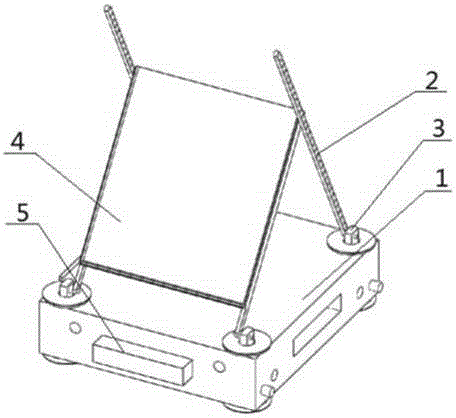
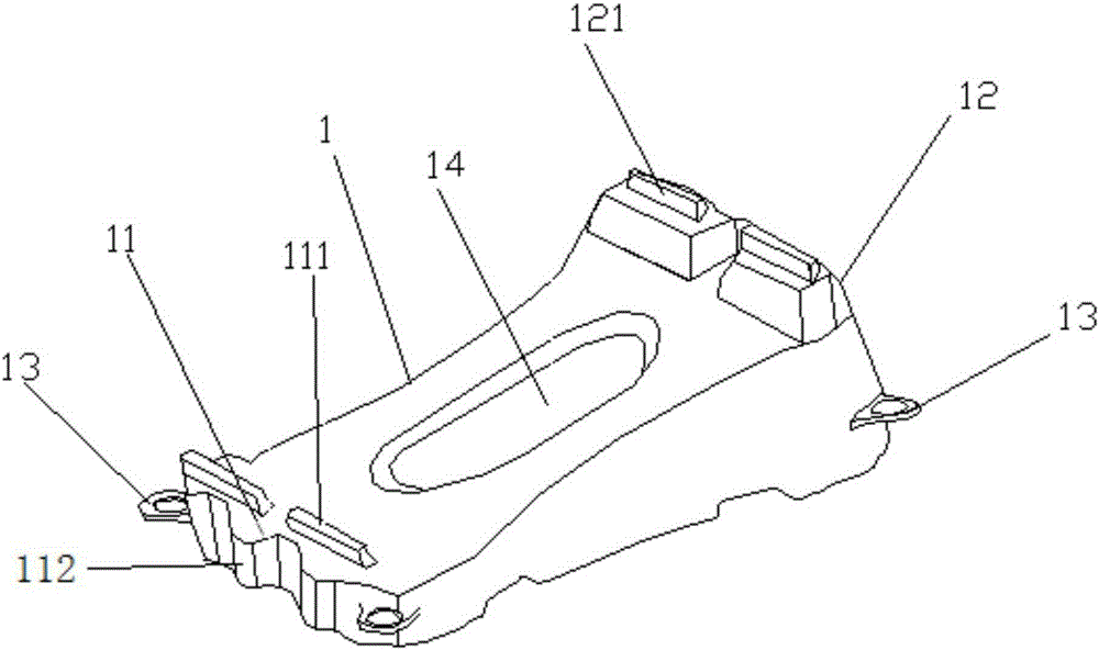
[0037] Such as Figure 3 to Figure 6 As shown, the floating body for the floating photovoltaic power station of this embodiment includes a floating body body 1 that can float on the water, such as image 3 As shown, the floating body 1 includes a first end 11 and a second end 12, the upper surface of the first end 11 is lower than the upper surface of the second end 12, so that the first end 11 and the second end Form a slope between 12. The inclination between the first end and the second end is determined according to the latitude of the location of the photovoltaic power station, which is about latitude +5 or +10, and the specific inclination value can refer to the empirical value on land.

[0038] Such as image 3 As shown, the upper surface of the floating body near the first end is provided with two first buckles 111 for detachably connecting with the two first clips on the back of the photovoltaic panel of the photovoltaic power station, near the second end Two secon...

Embodiment 2

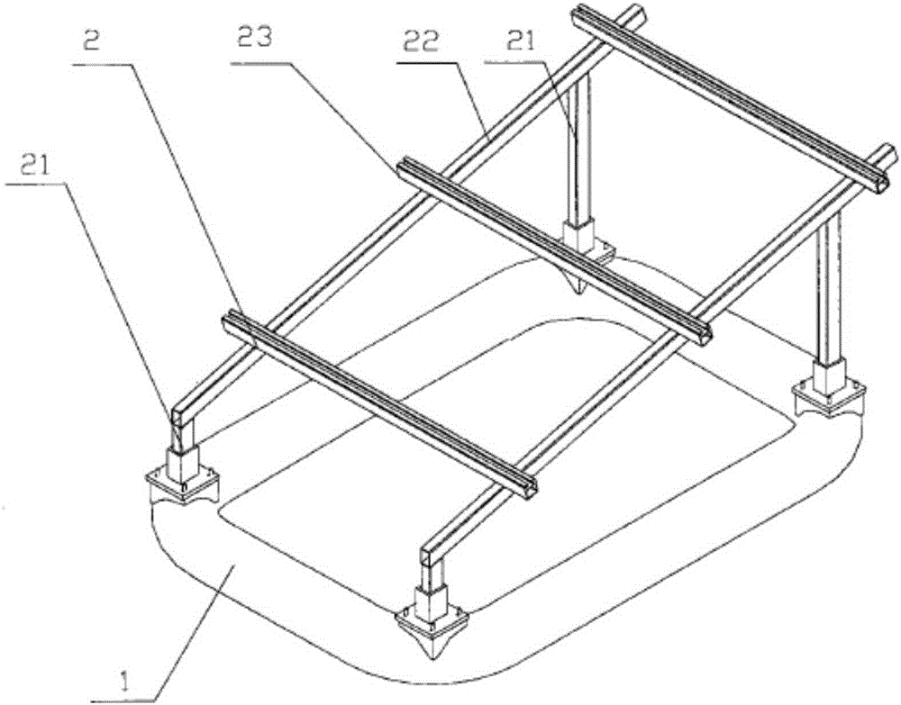
[0054] Embodiment 2 also discloses the connection method of the floating body described in Embodiment 1. The floating bodies 1 are spaced apart from the connecting floating bodies 2, and the floating bodies 1 pass through such as Figure 5 The shown connection floating body 2 is connected as a whole. Specifically, such as Image 6 As shown, the connecting floating body 2 is provided with lugs 21 , the connecting lugs 13 on the floating body body 1 and the lugs 21 are connected as a whole through the connecting bolts 3 , and the photovoltaic panel is snapped onto the floating body body through buckles. With this connection method, there is a certain interval between the floating body bodies. Due to the interval between adjacent floating body bodies, there is a large space for ventilation and heat dissipation between the photovoltaic panels and the floating body bodies, which expands the effective use of photovoltaic panels. The heat dissipation area improves the heat dissipat...


PUM


Abstract

The invention discloses a floating member used for a waterborne photovoltaic power station and a connection method thereof. The floating member at least comprises a floating member body which can be floated on water. The floating member body comprises a first end part and a second end part. Height of the upper surface of the first end part is lower than that of the upper surface of the second end part. The upper surface of the floating member body, which is close to the first end part, is provided with a first connection structure which is used for being detachably connected with the first connection piece of the back surface of a photovoltaic panel. The upper surface of the floating member body, which is close to the second end part, is provided with a second connection structure which is used for being detachably connected with the second connection piece of the back surface of the photovoltaic panel. Height of the upper surface of the first end part of the floating member body is set to be higher than that of the upper surface of the second end part, and the connection structures connected with the photovoltaic panel are directly arranged on the upper surface of the floating member body so that the installing technology of the photovoltaic power station can be greatly simplified, installing time can be saved and installing cost can be reduced.

Description

technical field [0001] The invention relates to a floating body used on water, in particular to a floating body used in a photovoltaic power station on water and a connection method thereof. Background technique [0002] With the depletion of non-renewable energy such as oil and gas, human beings pay more and more attention to the development and application of renewable energy. Solar energy has become an important part of renewable energy used by human beings. It is an ideal new energy and hopes to get Further development and utilization. [0003] Photovoltaic power generation uses the photovoltaic effect of the semiconductor interface to directly convert light energy into electrical energy. Photovoltaic power stations have the advantages of no need to consume fuel, safety and reliability, no noise, no pollution emissions, and short construction period. But the photovoltaic power station not only occupies a large area, but also changes the nature and attributes of the lan...

Claims


Application Information

Patent Timeline
Patent Type & Authority Applications(China)
IPC IPC(8): H02S10/00B63B35/44
CPCY02E10/50
Inventor 孔飞
Owner SHANGHAI QIHUA WHARF ENG CO LTD
Why Eureka
Try Eureka