Two-part steel piston, joining process

A two-piece, piston technology, applied in the direction of piston, assembly from parts, engine components, etc., can solve problems such as consumption and achieve the effect of stable connection

Inactive Publication Date: 2015-12-23
KOLBENSCHMIDT AG
View PDF7 Cites 2 Cited by
  • Summary
  • Abstract
  • Description
  • Claims
  • Application Information

AI Technical Summary

Problems solved by technology

This is very costly in operation

Method used


Image

  • Two-part steel piston, joining process
  • Two-part steel piston, joining process
  • Two-part steel piston, joining process

Examples


Embodiment Construction

[0028] In the following description of the figures, terms such as top, bottom, left, right, front, rear etc. refer only to the selected exemplary illustrations and positions of the devices and other elements in the corresponding figures. These concepts are not to be understood as limiting, ie the references can be changed by different positions and / or mirror-symmetrical designs etc.

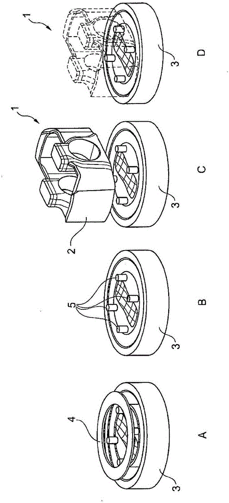
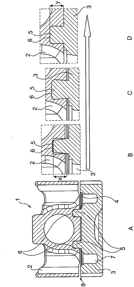
[0029] figure 1 A to 2D illustrate the joining process according to the invention using the example of a cooling channel piston. The method is not limited to cooling channel pistons, pistons without cooling channels can also be produced according to the method according to the invention.

[0030] all figure 1 A to ID show plan views of the underside (in the operating position) of the upper part 3 of the piston blank 1 .

[0031] exist figure 1 In A, the ring 4 for forming the cooling channel 7 is inserted into the upper part 3 at the top end. When the lower part 2 is then provided and the co...


PUM


Abstract

The invention relates to a piston (10), in particular a cooling channel piston, for an internal combustion engine, comprising at least one lower part (2) and one upper part (3), a combustion chamber (13) and at least one annular groove (11), wherein the upper part (3) or the lower part (2) is fastened by means of at least one undercut on the lower part (2) or on the upper part (3), characterised in that the upper part (3) comprises at least one combustion chamber (13) and at least one annular groove (11). The invention further relates to a method for producing such a piston.

Description

technical field [0001] The invention relates to a piston according to the features stated in the respective preambles of the independent claims and to a method for manufacturing a two-part piston comprising an upper part and a lower part. Background technique [0002] EP1878902A2 describes the construction of a piston comprising an upper part and a lower part, which are supported and connected to each other in the area of ​​the contact area by means of engaging slats. In this case, a clamping connection, like a coupling, is produced by twisting the upper part relative to the lower part. This is very costly in operation. [0003] It is known from DE 10 2005 030 556 B4 to produce a connection between an upper part and a lower part of a piston for an internal combustion engine by means of a positive fit. Here, it is disadvantageous that the upper part, which engages with a positive fit, only forms part of the piston crown. [0004] The piston, in particular the cooling chann...

Claims


Application Information

Patent Timeline
Patent Type & Authority Applications(China)
IPC IPC(8): F02F3/00F02F3/22
CPCB21K25/00F02F3/003F02F3/22F02F3/0015F02F3/0092
Inventor R·屈内尔
Owner KOLBENSCHMIDT AG
Why Eureka
Try Eureka