Stabilizer used between spine plates

A stabilizer and spine plate technology, which is applied to spinal implants and other directions, can solve the problems of difficult installation, easy relaxation, and large intraoperative trauma, and achieve the effects of firm and reliable fixation, stress dispersion, and convenient implantation.

Active Publication Date: 2015-12-30
BIODA DIAGNOSTICS WUHAN
View PDF10 Cites 12 Cited by
  • Summary
  • Abstract
  • Description
  • Claims
  • Application Information

AI Technical Summary

Problems solved by technology

However, there are still many defects in the existing interspinous process or interspinous plate dynamic stabilizers, such as some cannot accurately match the thickness of the spinous process, some prostheses and spinous process collisions cause wear and tear reactions, and some connections are complicated ( Such as the interspinous universal dynamic stabilizer), and some fixators are too bulky, cause large intraoperative trauma, occupy a lot of space in the postoperative body, and are difficult to install (such as the interspinous universal dynamic stabilizer), or some are fixed with screws There is a risk of loosening, or some use a long-term fixation strap to loosen easily, and some installations require more bone resection, or the supraspinous ligament needs to be resected or incised (such as Coflex, interspinous universal stabilizer ) and other issues, it is difficult to guarantee low complications and good long-term effects

Method used


Image

  • Stabilizer used between spine plates
  • Stabilizer used between spine plates
  • Stabilizer used between spine plates

Examples


Embodiment Construction

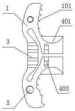
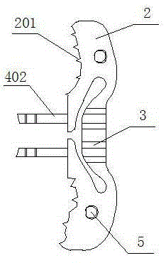
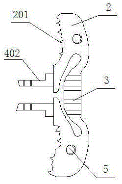
[0036] The inter-ratchet stabilizer includes an opening fixing plate 1, a buckle fixing plate 2, an elastic structure 3 and a snap-in device 4, the elastic structure 3 is respectively placed in the middle of the opening fixing plate 1 and the buckling fixing plate 2, and the opening fixing plate 1 It is connected with the buckle fixing plate 2 through a snap-in device 4 . After the connection, the connecting plate 402 can be deformed with anti-loosening screws or a bender to reinforce the connected clamping device 4 .

[0037]The clamping device 4 is composed of a ferrule 401 and a connecting plate 402, the ferrule 401 is located in the middle of the opening fixing plate 1, and the ferrule 401 is a hollow structure; the connecting plate 402 is located in the middle of the buckle fixing plate 2, and the connecting plate 402 The outer end of the screw hole or slot 404 is made, and the ferrule 401 is correspondingly made with a screw hole or a slotted hole 403; the ferrule 401 an...


PUM


Abstract

The invention relates to a stabilizer used between spine plates, and belongs to the technical field of medical instruments, particularly, human insertions. The stabilizer comprises an opening fixing plate, a buckle fixing plate and elastic structures, wherein the elastic structures are respectively arranged at the middle parts of the opening fixing plate and the buckle fixing plate; the opening fixing plate and the buckle fixing plate are connected through a clamping device, and are further fixed through movable inserting plates; the elastic structures comprise U-shaped structures and torsion structures. The stabilizer can realize elastic stability of stretching, bending, side bending and rotating of spine operation sections as well as dynamic stability of circumduction formed by multidirectional activity synthetic action, has the characteristics of being disperse in stress, convenient to implant and strong in matching ability with spinous process thickness and spine interval, and can be used for cases with oversize lumbosacral angles, over short spinous processes or undersize spine intervals; the problem that in the conventional various fixture techniques applied to the dynamic spinous processes, the supraspinal ligaments need to be excised or incised, the fixing is unreliable, the activity in various directions cannot be elastically limited, the matching ability with the spinous processes is poor, and negative damage in the operation is large are solved.

Description

technical field [0001] The invention relates to a stabilizer between spine plates, which belongs to the technical field of implants in human body of medical instruments. Background technique [0002] At present, spinal fusion technology has achieved good results in the treatment of neck and back pain and instability of the cervical and lumbar spine, with a fusion rate of over 90%. However, studies have shown that its clinical efficacy has not reached the corresponding expectations; moreover, rigid internal fixation and spinal fusion may cause complications such as accelerated degeneration of adjacent segments, internal fixation failure, and postoperative pseudarthrosis formation. In view of this, dynamic fixation of the spine is becoming a popular technology in the treatment of degenerative cervical and lumbar diseases in recent years, and it is also one of the important development directions of spinal surgery in the future, including artificial total intervertebral disc re...

Claims


Application Information

Patent Timeline
Patent Type & Authority Applications(China)
IPC IPC(8): A61F2/44
Inventor 李照文
Owner BIODA DIAGNOSTICS WUHAN
Why Eureka
Try Eureka