Biological control ball releasing device matched with airplane

A technology of throwing device and small ball, applied in aircraft parts, launching device, transportation and packaging, etc., can solve the problems of large space occupation, reduced labor intensity, prone to extrusion, collision, etc., to achieve a stable center of gravity and reduce labor the effect of strength

Active Publication Date: 2015-12-30
JIANGSU UNIV
View PDF17 Cites 27 Cited by
  • Summary
  • Abstract
  • Description
  • Claims
  • Application Information

AI Technical Summary

Problems solved by technology

[0004] But the release of natural enemy insects mostly adopts artificial fixed-point release, such as patent application number "200610017085. Bag-type bee release device", application number "200620029161.4" is named "Trichogramma box-type bee release device", application number "201210074834.8" is named "a method for sustainable release of parasitic natural enemy insects", application number "201310567933.4" The bee release device or the release device invented by the name "Insect and Bug Release Device and Its Application", the application number "201320407816.7" and the name "A Multipurpose Natural Enemy Insect Mixing Release Device" all need to be placed manually or Hanging in the field, because for the integrated large field, the labor intensity is very high; in addition, the patent application number "201120502819. Method and release device for releasing parasitoids to control pests", application number "201320503873.5" titled "a bee release device suitable for releasing parasitoids in paddy fields to control rice pests", application number "201420451209.5" titled "a device suitable for releasing natural enemies "Insect pest control device" only invented the release device for natural enemy insects, did not indicate how to release them into the field, and did not invent a supporting mechanical release mechanism
[0005] In order to reduce the labor intensity of releasing natural enemies and improve delivery efficiency, the patent application num

Method used


Image

  • Biological control ball releasing device matched with airplane
  • Biological control ball releasing device matched with airplane
  • Biological control ball releasing device matched with airplane

Examples


Embodiment Construction

[0028]The present invention will be further described below in conjunction with the accompanying drawings and specific embodiments.

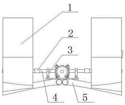
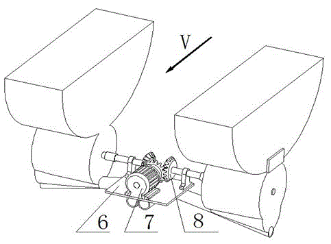
[0029] Such as figure 1 As shown, a kind of biological control ball delivery device supporting the aircraft is characterized in that it includes a small ball delivery device 1, a coupling 2, a shaft seat 3, a transmission shaft 4, an air intake duct 5, a mounting plate 6, a motor 7. Bevel gear 8; after the motor 7 rotates, the bevel gear 8 is driven to provide power for the small ball delivery device 1 through the transmission shaft 4, and the speed of the transmission shaft 4 can be adjusted by adjusting the speed of the motor 7 .

[0030] Such as Figure 6 , 7 , 8, the transmission shaft 4 drives the outer sheave 102 to rotate through the shaft coupling 2, and the outer sheave 102 is provided with a ball-taking groove 1021; the ball 9 in the ball storage chamber 1011 falls into Take the ball groove 1021 and rotate with the outer sheave 102,...


PUM


Abstract

The invention discloses a biological control ball releasing device matched with an airplane, which relates to the field of agricultural plant protection machinery. Two ball releasing devices are arranged at two sides of the airplane, so that the stability of the gravity center of the airplane is guaranteed; when the whole device works, a motor drives outer groove wheels in the left and right ball releasing devices to rotate, and the outer groove wheels drive the balls to reach a cylindrical ball guiding groove, and then the balls are discharged from the ball releasing devices; in addition, the releasing amount of the balls is regulated by regulating the rotating speed of the motor or the length of a ball releasing groove baffle; the left-right space between every two balls reaching the ground is regulated by regulating the size of an air inlet of an air inlet pipeline; the whole device realizes mechanical releasing of natural enemy insects in biological control, so that labor intensity is greatly reduced.

Description

technical field [0001] The invention relates to the field of agricultural plant protection machinery, in particular to a biological control pellet delivery device matched with an aircraft. Background technique [0002] The control of crop diseases and insect pests is an important part of agricultural production and harvest; according to the statistics of foreign experts, if no preventive measures are taken, the damage caused by diseases and insect pests is about 30% of the total output value of agricultural products. Chemical control and mechanical spraying are still the mainstay of plant protection operations. The main method, but it brings huge environmental problems; the United States, the United Kingdom and other member states and regions of the European Community with a relatively high level of agricultural machinery, the effective utilization rate of pesticides has reached 60%-70%, In China, only 30%; China has 1 million tons of pesticide preparations and 100 million t...

Claims


Application Information

Patent Timeline
IPC IPC(8): B64D1/02
Inventor 邱白晶周海涯
Owner JIANGSU UNIV
Why Eureka
Try Eureka