Gearshift mechanism of harvesting machine, gearshift control system and harvesting machine with gearshift mechanism

A technology of harvesting machinery and gear shifting mechanism, which is applied in the direction of mechanical equipment, transmission device control, and components with teeth, etc. It can solve the problems of cumbersome gear shifting and inconvenient operation, and achieve the effect of reducing driving fatigue and convenient gear shifting

Inactive Publication Date: 2015-12-30
ZOOMLION HEAVY MASCH CO LTD
View PDF8 Cites 0 Cited by
  • Summary
  • Abstract
  • Description
  • Claims
  • Application Information

AI Technical Summary

Problems solved by technology

[0003] In the process of realizing the present invention, the inventor found that the prior art has at least the following problems: since the hydraulic motor is used to provide power to the gearbox, and the power of the motor is provided by a hydraulic pump, when shifting gears, the pump must first be in the Neutral position (that is, cut off the motor power), and then you can shift gears manually
Changing gears is cumbersome and inconvenient to operate

Method used


Image

  • Gearshift mechanism of harvesting machine, gearshift control system and harvesting machine with gearshift mechanism
  • Gearshift mechanism of harvesting machine, gearshift control system and harvesting machine with gearshift mechanism
  • Gearshift mechanism of harvesting machine, gearshift control system and harvesting machine with gearshift mechanism

Examples


Embodiment 1

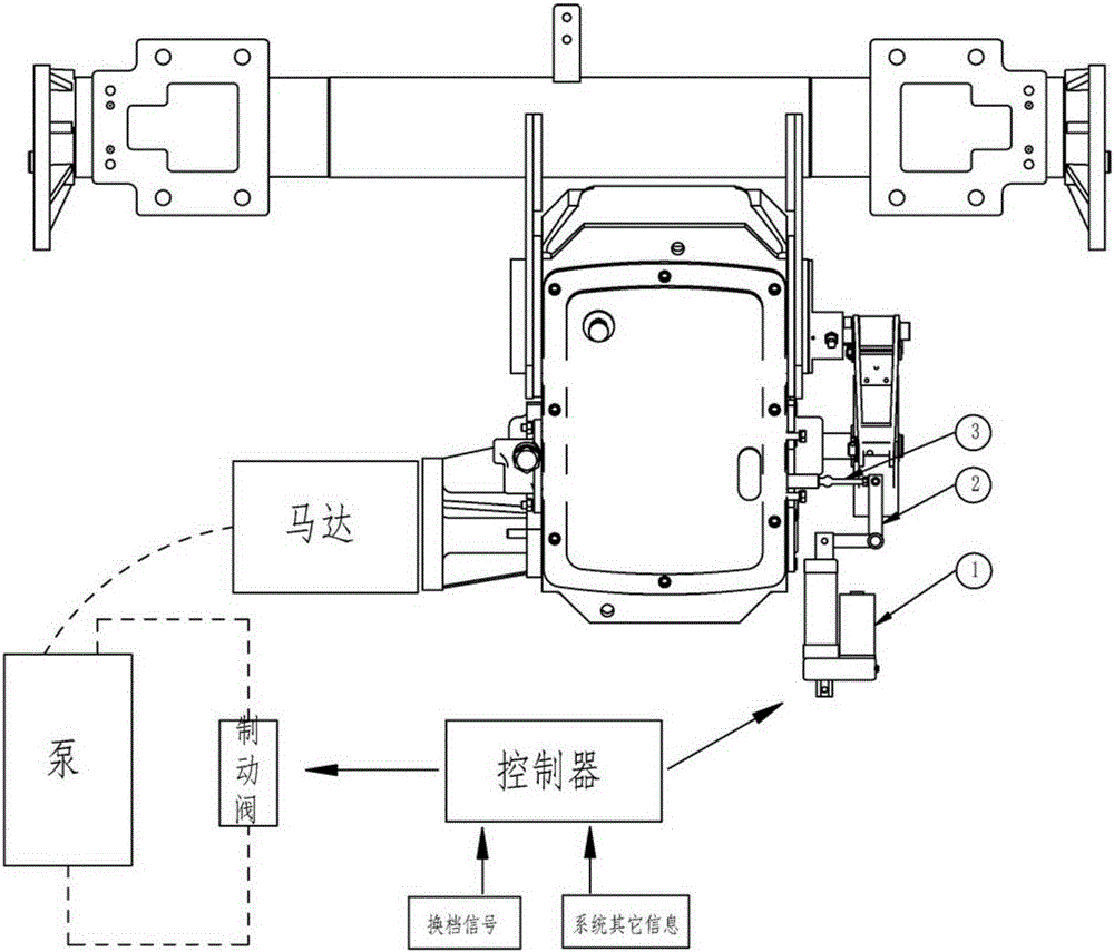
[0038] see figure 1 , a gear shifting mechanism for a harvesting machine, having:

[0039] The driving rod 2, the driving part and the connecting rod 3 are rotatably set on the shaft on the body near the middle part of the driving rod 2; the end of the driving part is hinged to the first end of the driving rod 2; the first end of the connecting rod 3 is connected to the The second end of the rod 2 is hinged, and the second end of the connecting rod 3 is connected with the shift point of the gearbox of the body. The driving part is controlled by the controller, and one end of the driving rod 2 is pushed by the driving part to make the driving rod 2 rotate around the axis, and the other end of the driving rod 2 drives the connecting rod 3 to move, and the connecting rod 3 is connected to the shift point of the gearbox, thereby changing the transmission The position of the shift point to achieve the purpose of shifting. The shifting is realized by controlling the movement of th...

Embodiment 2

[0049] This embodiment is a further improvement made on the basis of the first embodiment. For the same parts as the first embodiment, reference may be made to the first embodiment, which will not be repeated here.

[0050] power input

[0051] like figure 1 As shown, the gearbox used in this system is a commonly used two-speed gearbox, the drive mode is hydraulic drive, and the left side is a pump-motor drive mode. A brake pump, the brake pump is a solenoid valve, the switch is controlled by the controller. This valve is in the normal state (closed state) and the pump outputs normally, driving the motor to work. When this valve works, the output of the pump is blocked and the motor loses power.

[0052] executive body

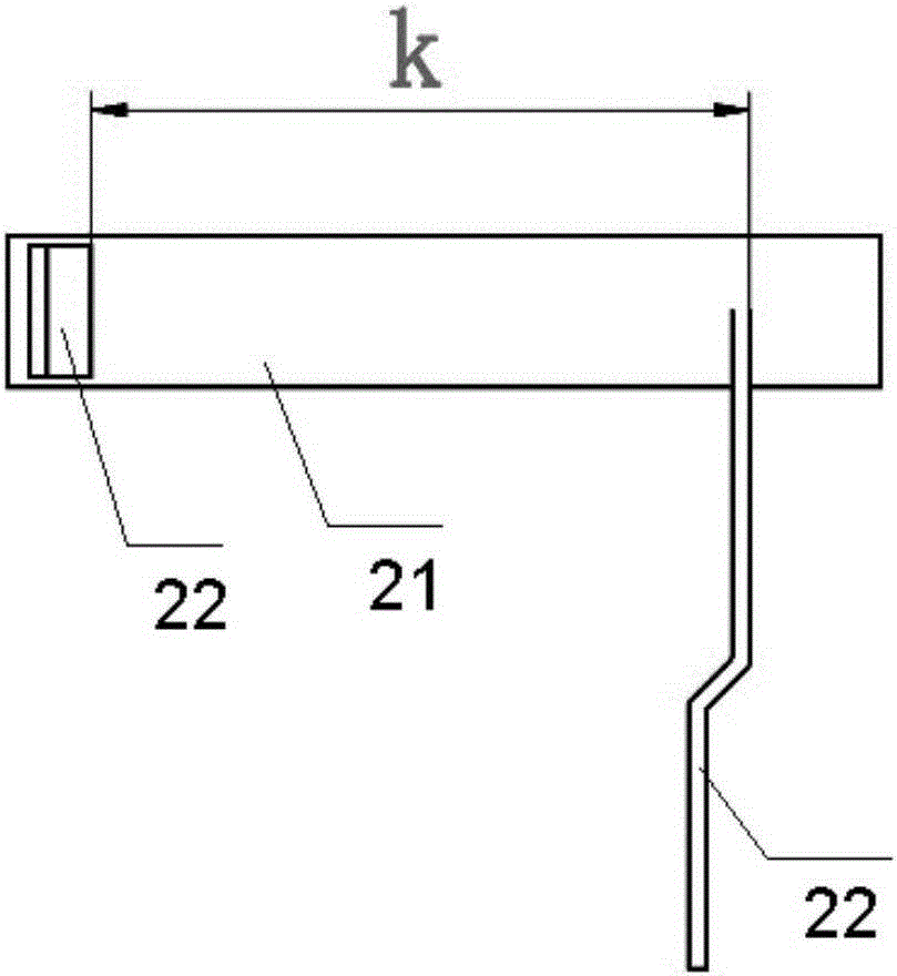
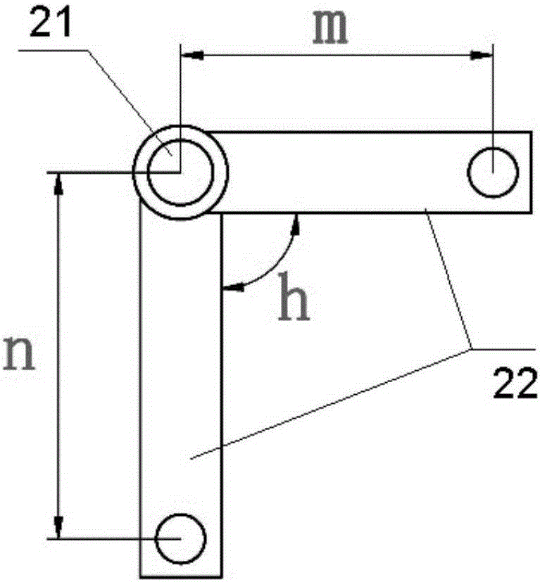
[0053] like Figure 4 As shown, the electric push rod 1 can be stretched out or retracted, and can send a telescopic length signal. The driving force and telescopic length of the electric push rod 1 need to be calculated and selected according to needs. ...


PUM


Abstract

The invention discloses a gearshift mechanism of a harvesting machine, a gearshift control system and a harvesting machine with the gearshift mechanism. The gearshift mechanism is provided with a shift lever (2), a driving component and a connecting rod (3), wherein the nearby part of the middle part of the shift lever (2) is rotatablely sheathed on the shaft of a machine body; the driving component is controlled by a controller; the end of the driving component is hinged with a first end of the shift lever (2); a first end of the connecting rod (3) is hinged with a second end of the shift lever (2); and a second end of the connecting rod (3) is connected with a transmission case gearshift point of the machine body. The driving component drives one end of the shift lever (2), so that the shift lever (2) rotates around the shaft, the other end of the shift lever (2) drives the connecting rod (3) to move, and the connecting rod (3) is connected with the transmission case gearshift point, thereby changing the position of the transmission case gearshift point and achieving the goal of gearshift. The motion of the driving component is controlled to implement gearshift, and the driving component is automatically controlled by the controller, so that the gearshift is convenient, reliable and intelligent, thereby lowering the driving fatigue.

Description

technical field [0001] The invention belongs to the technical field of agricultural machinery, and in particular relates to a shifting mechanism of a harvesting machine, a shifting control system thereof and a harvesting machine with the same. Background technique [0002] Harvesting machinery driven by hydraulic pressure has the advantages of low noise and infinitely variable speed, and is more and more popular among users. The shifting mode of the gearbox used in this model still adopts traditional cable or mechanical structure control. [0003] In the process of realizing the present invention, the inventor found that the prior art has at least the following problems: since the hydraulic motor is used to provide power to the gearbox, and the power of the motor is provided by a hydraulic pump, when shifting gears, the pump must first be in the Neutral position (that is, cut off the motor power), and then you can shift gears manually. Shifting gears is cumbersome and inco...

Claims


Application Information

Patent Timeline
IPC IPC(8): F16H61/02F16H63/30
CPCF16H61/0204F16H63/30F16H2306/00
Inventor 张恒
Owner ZOOMLION HEAVY MASCH CO LTD
Why Eureka
Try Eureka