A matrix switching system and matrix switching method for multi-format video signal switching

A video signal and matrix switching technology, applied in the field of video and audio, security, can solve the problems of signal security, real-time concerns, cumbersome wiring, short transmission distance, etc., to achieve the effect of convenient long-distance transmission and simplified use

Active Publication Date: 2018-06-19
大连科迪视频技术有限公司
View PDF5 Cites 0 Cited by
  • Summary
  • Abstract
  • Description
  • Claims
  • Application Information

AI Technical Summary

Problems solved by technology

[0002] In the audio-visual system and security system, the matrix switcher is an indispensable device; especially with the emergence of a variety of front-end signal sources, multi-format matrixes have emerged as the times require, which greatly facilitates the integration and installation of the system; but the signal acquisition end There are often many uncertainties in the distance to the equipment control room. The short distance is less than a few meters, and the distance is more than thousands of kilometers. Even if the best coaxial cable is used, the high-definition signal can only be transmitted to a few hundred meters. distance; if the IP network known for its long-distance transmission is used, there are concerns about signal security and real-time performance
[0003] At the same time, the control of the signal acquisition terminal, the front-end equipment of the matrix switcher, is also a relatively important link. In view of the fact that the control interface is generally a general-purpose RS485; so general applications require another control signal line dedicated to the transmission of 485 control signals; and there are often Problems such as short transmission distance and cumbersome wiring

Method used


Image

  • A matrix switching system and matrix switching method for multi-format video signal switching
  • A matrix switching system and matrix switching method for multi-format video signal switching
  • A matrix switching system and matrix switching method for multi-format video signal switching

Examples


Embodiment Construction

[0041] In order to make the object, technical solution and advantages of the present invention clearer, the present invention will be further described in detail below in conjunction with the accompanying drawings.

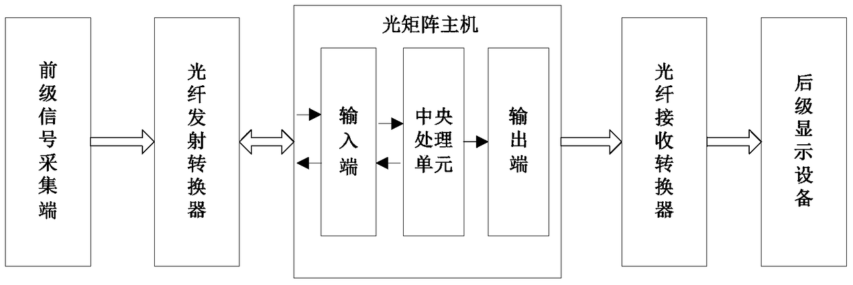
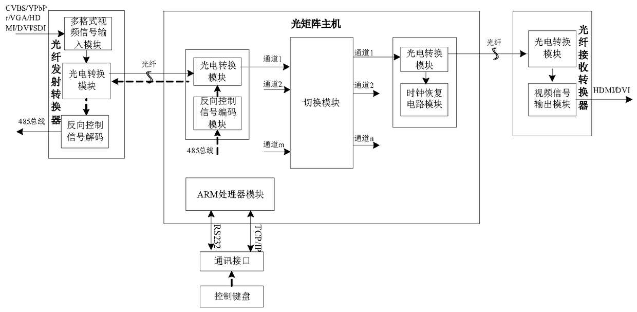
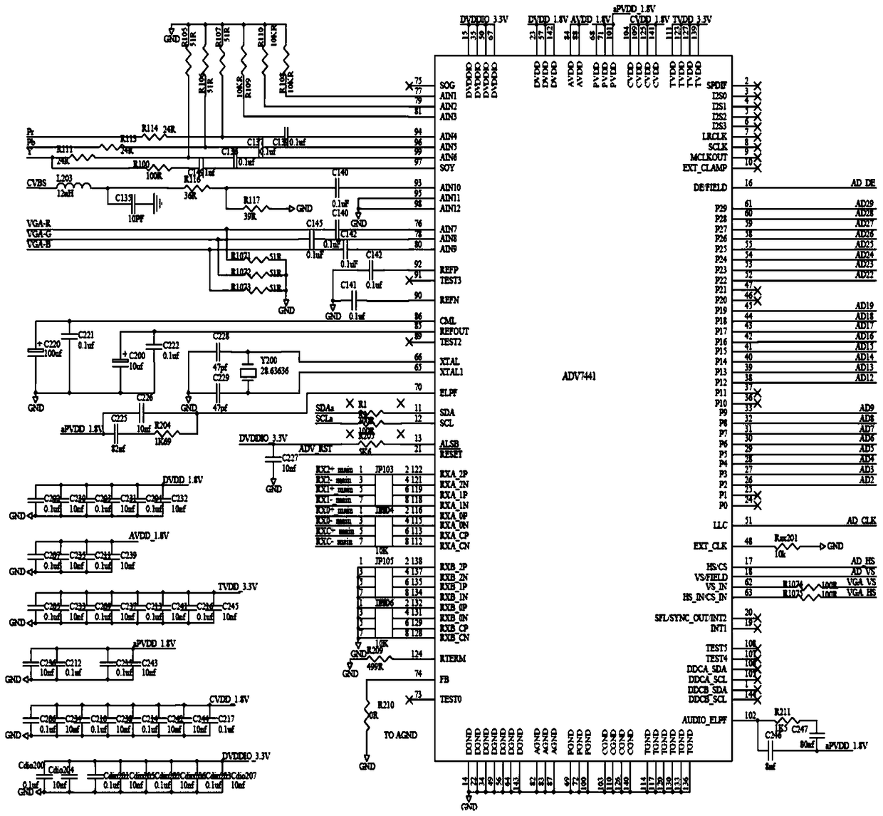
[0042] Such as figure 1 — Figure 10 As shown, the present invention proposes an optical matrix system for multi-format video signal switching, which meets the needs of the audio, video and security industries for long-distance real-time transmission of multi-format video signals.

[0043] The current common multi-format matrix greatly facilitates the switching processing of video and audio signals at the signal acquisition end of different types of interfaces, but the distance between the signal acquisition end and the equipment control room varies, and common metal cables often cannot meet the signal distance. The need for distance transmission, and the security and real-time performance of optical signals just make up for this need; so the optical fiber matrix...


PUM


Abstract

The invention discloses a matrix switching system and a matrix switching method for multi-format video signal switching. The system includes identifying multi-format video signals, converting them into unified optical signals and sending them to an optical matrix host, and A fiber optic launch converter that receives control data in the form of optical signals for reverse transmission; it is used to complete the video signal conversion and transmission process and synchronously converts the control data corresponding to the video signal into optical signals during the video signal conversion and transmission process and then reverses the transmission The optical matrix host to the optical fiber transmitting converter; and the optical fiber receiving converter used to convert the optical signal sent by the optical matrix host into a video signal in the form of an electrical signal that can be recognized by the subsequent display device. In the present invention, the input and output signals of each channel are independent of each other, and if one of the signals fails, it will not affect the signal transmission of other channels; at the same time, the synchronous transmission of reverse data in the optical fiber can effectively solve the problem that the control signal needs to be transmitted through a special cable problems and other advantages.

Description

technical field [0001] The invention relates to the field of video and audio technology and the field of security technology, in particular to a matrix switching system and a matrix switching method for switching multi-format video signals. Background technique [0002] In the audio-visual system and security system, the matrix switcher is an indispensable device; especially with the emergence of a variety of front-end signal sources, multi-format matrixes have emerged as the times require, which greatly facilitates the integration and installation of the system; but the signal acquisition end There are often many uncertainties in the distance to the equipment control room. The short distance is less than a few meters, and the distance is more than thousands of kilometers. Even if the best coaxial cable is used, the high-definition signal can only be transmitted to a few hundred meters. If the IP network known for its long-distance transmission is used, there are concerns ab...

Claims


Application Information

Patent Timeline
Patent Type & Authority Patents(China)
IPC IPC(8): H04N5/268H04N7/22
Inventor 马庆强周春雷
Owner 大连科迪视频技术有限公司
Why Eureka
Try Eureka