
Automatic insect eliminating and killing lamp

An insect-clearing and insect-killing lamp, automatic technology, applied in the field of insect-killing lights and automatic insect-clearing and insect-killing lights, can solve problems such as inability to clear insects, low efficiency of insect clearing, and loose traction ropes, so as to reduce the interference of insect corpses , Good insect removal effect, not easy to shift

Active Publication Date: 2016-01-06
徐昌春
View PDF8 Cites 10 Cited by
  • Summary
  • Abstract
  • Description
  • Claims
  • Application Information

AI Technical Summary

Problems solved by technology

However, because it is controlled by a timing chip, the efficiency of cleaning insects is low. In addition, the brush is lifted and lowered by the traction rope and the motor. After a long time of use, the traction rope is easy to loosen, resulting in inaccurate positioning of the brush when it is lifted and lowered. Affect the effect of cleaning insects, especially when the deformation of the traction rope is large, the brush will come out of the high-voltage grid when it moves down, and it will get stuck when the brush rises again. In addition, the existing switch devices for controlling the up and down of the brush are all It is set under the lamp cap, and most of them are set on the insect collecting tray. When the switch device is set at the above position, it is often affected by rain, sunlight, insect corpses and dust, etc., resulting in damage to the switch and unable to perform normal insect cleaning work.

Method used


Image

  • Automatic insect eliminating and killing lamp
  • Automatic insect eliminating and killing lamp
  • Automatic insect eliminating and killing lamp

Examples


Embodiment Construction

[0026] The following are specific embodiments of the present invention and in conjunction with the accompanying drawings, the technical solutions of the present invention are further described, but the present invention is not limited to these embodiments.

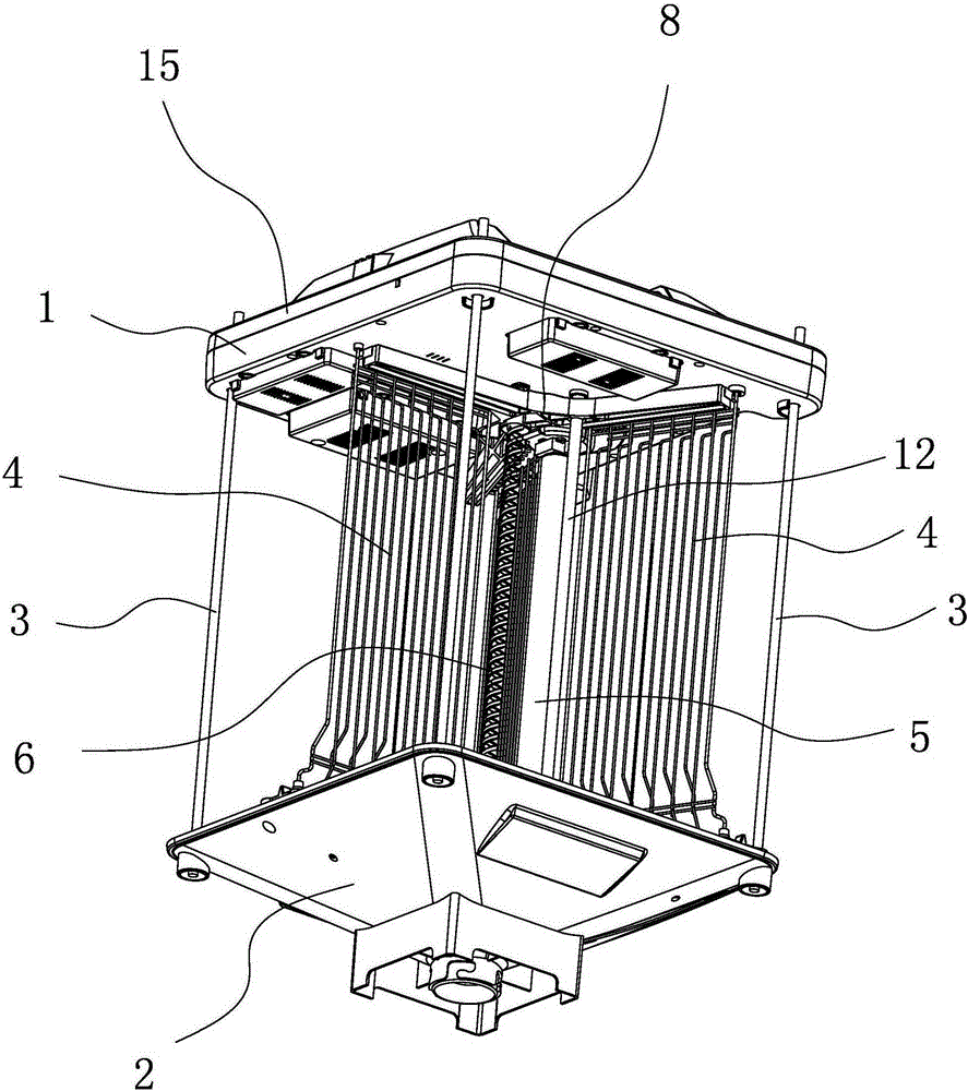
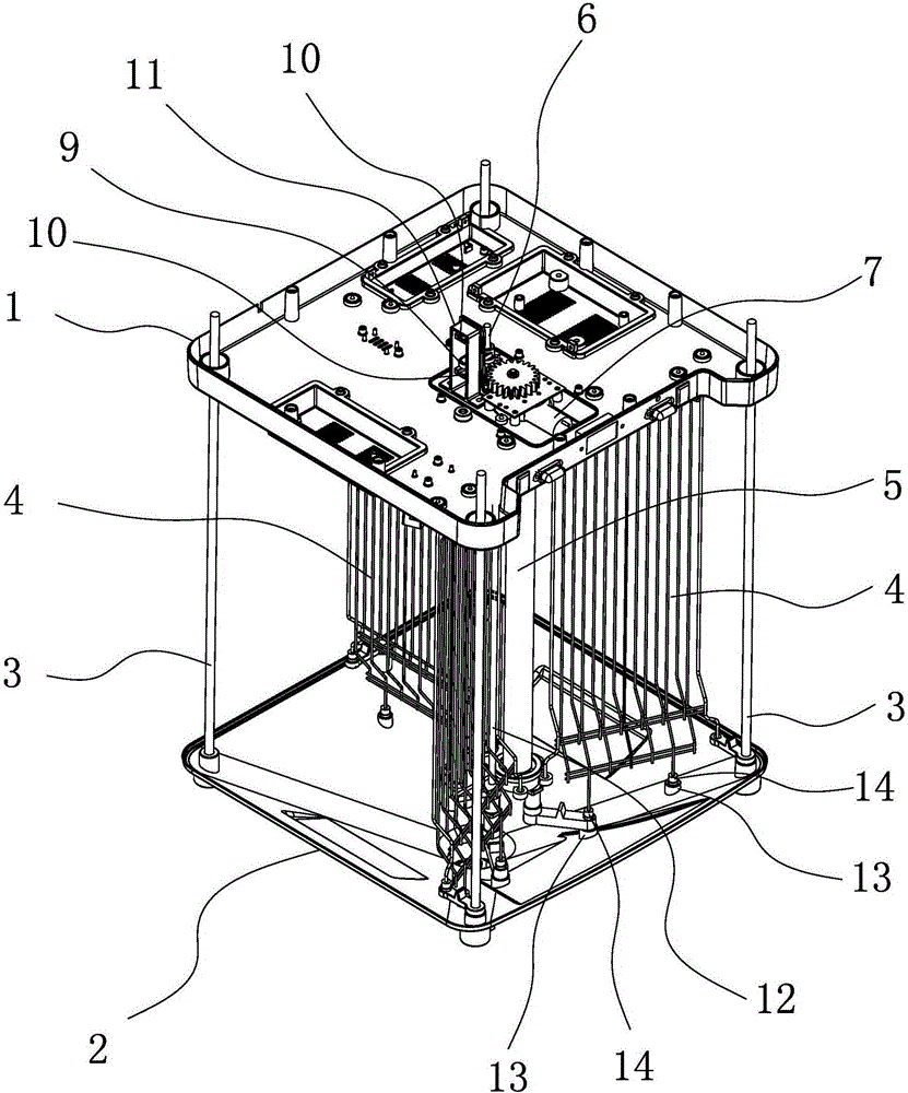
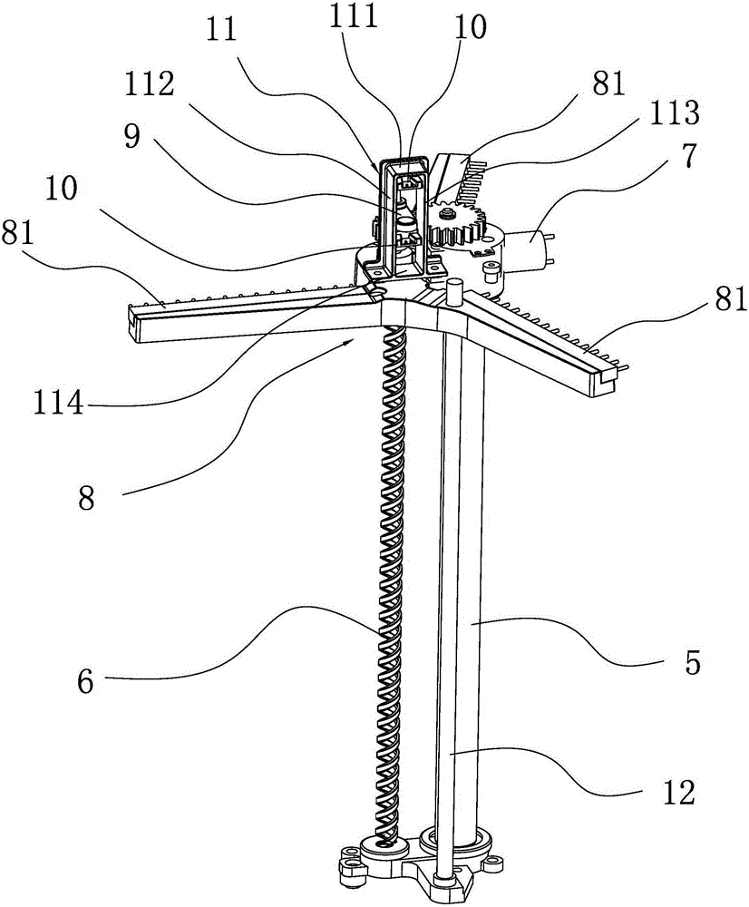
[0027] refer to figure 1 and figure 2 , the present embodiment is an automatic insect-clearing and exterminating lamp, comprising an upper lamp cap 1, a top cover 15 and an insect collecting tray 2, the top cover 15 covers the upper lamp cap 1, and the upper lamp cap 1 and the top cover 15 There is a cavity between them, the insect collecting tray 2 is located under the upper lamp cap 1 and the two are connected by a column 3, a high-voltage grid 4 is arranged between the upper lamp cap 1 and the insect collecting tray 2, and the lower end of the upper lamp cap 1 is provided There is an insect-attracting light source 5, and the high-voltage grid 4 is radially arranged with the insect-attracting light source 5 as the cent...


PUM


Abstract

The invention provides an automatic insect eliminating and killing lamp which belongs to the technical field of insect killing equipment. The automatic insect eliminating and killing lamp settles problems of low insect eliminating effect of an existing insect killing lamp and easy damage of an induction switch of the insect killing lamp. The automatic insect eliminating and killing lamp comprises an upper lamp cap, an insect collecting plate, a top cover, a lead screw, an insect eliminating wire brush bracket, a position induction rod, a position induction switch and a motor which is used for driving the lead screw to rotate. The lead screw is arranged on the upper lamp cap in a penetrating manner and furthermore the top of the lead screw upwards penetrates through the upper lamp cap. The insect eliminating wire brush bracket and the position induction rod are connected with the lead screw in a leadscrew-nut transmission manner. The position induction rod is arranged between the upper lamp cap and the top cover. The position induction switch is used for detecting the position of the position induction rod and makes the motor perform clockwise rotation or counter-clockwise rotation according to the position of the position induction rod. According to the automatic insect eliminating and killing lamp, automatic lifting of the insect eliminating wire brush bracket is realized; the position induction rod and the position induction switch are arranged in an inner chamber which is formed by the top cover and the upper lamp cap, thereby preventing influences of sunlight, rainwater, dust and insect bodies.

Description

technical field [0001] The invention belongs to the technical field of insect-killing equipment, and relates to an insect-killing lamp, in particular to an automatic insect-clearing and insect-killing lamp. Background technique [0002] The traditional method of agricultural pest control is often completed by spraying pesticides, but since pesticides will remain on crops, it poses a certain threat to human health. With the improvement of people's awareness of environmental protection and health, people begin to pay attention to physical insecticide. Light trapping and killing insects is an important technical means of integrated pest control. Traditional insecticidal lamps are composed of lamp caps, fluorescent tubes, insect collecting shells, base plates, high-voltage grids, and connecting seats. According to the phototaxis of pests, Insects are introduced by fluorescent tubes and killed by high-voltage power grids. After the pests are killed, insect corpses are easy to acc...

Claims


Application Information

Patent Timeline
Patent Type & Authority Applications(China)
IPC IPC(8): A01M1/04A01M1/22
Inventor 徐昌春
Owner 徐昌春
Learn More