Tower crane position limiter structure

A technology of limiter and tower crane, applied in the field of machinery, can solve the problems such as the cantilever structure cannot control the moving distance, cannot effectively utilize work, reduce work efficiency, etc., and achieve the effect of being suitable for popularization, tight connection and improving work efficiency.

Inactive Publication Date: 2016-01-06
WUXI GANGSHENG HEAVY EQUIP CO LTD
View PDF3 Cites 2 Cited by
  • Summary
  • Abstract
  • Description
  • Claims
  • Application Information

AI Technical Summary

Problems solved by technology

[0003] At present, there are some shortcomings in many tower cranes. The cantilever structure cannot control the moving distance, which is very inconvenient to move, cannot effectively use its work, and reduces work efficiency.

Method used


Image

  • Tower crane position limiter structure
  • Tower crane position limiter structure

Examples


Embodiment

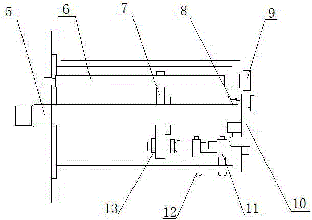
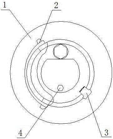
[0018] Example: such as Figure 1-2 As shown, a tower crane position limiter structure of the present invention includes a housing 1, a pressure plate 2, a bolt 3, a rubber ring 4, a screw rod 5, a guide rod 6, a moving nut 7, a bearing 8, a screw plug 9, an end cover 10, a limiter Bit switch 11, screw 12 and nut 13; Said housing 1 is equipped with a pressure plate 2 and said housing 1 is equipped with a guide rod 6; one side of said guide rod 6 is provided with a moving nut 7 located inside the housing 1 and the One end of the moving nut 7 is located on the side of the nut 13; a bolt 3 is installed at one end of the housing 1, and the top of the housing 1 is provided with a rubber ring 4 located on the side of the bolt 3; one end of the screw rod 5 is installed inside the end cover 10 And the end cover 10 is installed on one end of the casing 1 ; a limit switch 11 is arranged inside the casing 1 and the limit switch 11 is tightly connected by screws 12 .

[0019] As a techni...


PUM


Abstract

The invention provides a tower crane position limiter structure which comprises a shell, pressing plates, a bolt, a rubber ring, a screw rod, a guide rod, a movable nut, a bearing, a screw plug, an end cover, a limiting switch, screws and a nut. The pressing plates and the guide rod are arranged in the shell. The movable nut in the shell is arranged on one side of the guide rod, and one end of the movable nut is located on one side of the nut. The bolt is arranged at one end of the shell, and the rubber ring on one side of the bolt is arranged at the top end of the shell. One end of the screw rod is arranged in the end cover, and the end cover is arranged at one end of the shell. The limiting switch is arranged in the shell and is closely connected through the screws. The structure is stable and close in connection, and the tower crane position can be effectively limited by the limiting switch. Work efficiency is improved, use is facilitated, the service life is long, good social effects and economic benefits are achieved, and the structure is suitable for being used and popularized.

Description

technical field [0001] The invention relates to a tower crane position limiter, in particular to a tower crane position limiter structure, which belongs to the field of mechanical technology. Background technique [0002] A limit switch is an electrical switch used to limit the movement limit position of a mechanical device. There are contact and non-contact limit switches. The contact type is more intuitive. The upper travel switch is installed on the moving parts of the mechanical equipment, and the limit position stopper is installed on the fixed point of the relative movement, or the opposite installation position. When the mechanical contact of the limit switch hits the stopper, the control circuit is cut off, and the machine stops or changes its operation. Due to the mechanical inertial movement, this limit switch has a certain "overtravel" to protect the switch from damage. There are many forms of non-contact, the common ones are reed switch, photoelectric type, in...

Claims


Application Information

Patent Timeline
Patent Type & Authority Applications(China)
IPC IPC(8): B66C23/90
Inventor 陈大兴
Owner WUXI GANGSHENG HEAVY EQUIP CO LTD
Why Eureka
Try Eureka