
Oil-gas separation device and compressor comprising same

A separation device, oil and gas technology, applied in the field of compressors, can solve the problems of reduced compressor energy efficiency, poor separation effect, damage to the impeller, etc., to achieve complete separation, improve purity, and good separation effect

Inactive Publication Date: 2016-01-06
CHONGQING MIDEA GENERAL REFRIGERATING EQUIP
View PDF6 Cites 5 Cited by
  • Summary
  • Abstract
  • Description
  • Claims
  • Application Information

AI Technical Summary

Problems solved by technology

[0002] In the centrifugal compressor system, the filter with separate packing is mainly used, and the packing uses a general penetrating wire mesh, which has poor separation effect. During the operation, the oil mist will enter the impeller together with the refrigerant gas. The suction port will reduce the energy efficiency of the compressor and seriously damage the impeller

Method used


Image

  • Oil-gas separation device and compressor comprising same
  • Oil-gas separation device and compressor comprising same
  • Oil-gas separation device and compressor comprising same

Examples


Embodiment Construction

[0031] Embodiments of the present invention are described in detail below, examples of which are shown in the drawings, wherein the same or similar reference numerals designate the same or similar elements or elements having the same or similar functions throughout. The embodiments described below by referring to the figures are exemplary and are intended to explain the present invention and should not be construed as limiting the present invention.

[0032] In describing the present invention, it is to be understood that the terms "centre", "length", "width", "thickness", "upper", "lower", "vertical", "horizontal", "top", The orientation or positional relationship indicated by "bottom", "inner", "outer", etc. is based on the orientation or positional relationship shown in the drawings, and is only for the convenience of describing the present invention and simplifying the description, rather than indicating or implying the referred device Or elements must have a certain orien...


PUM


Abstract

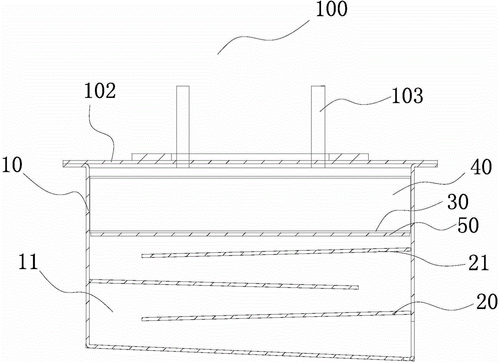
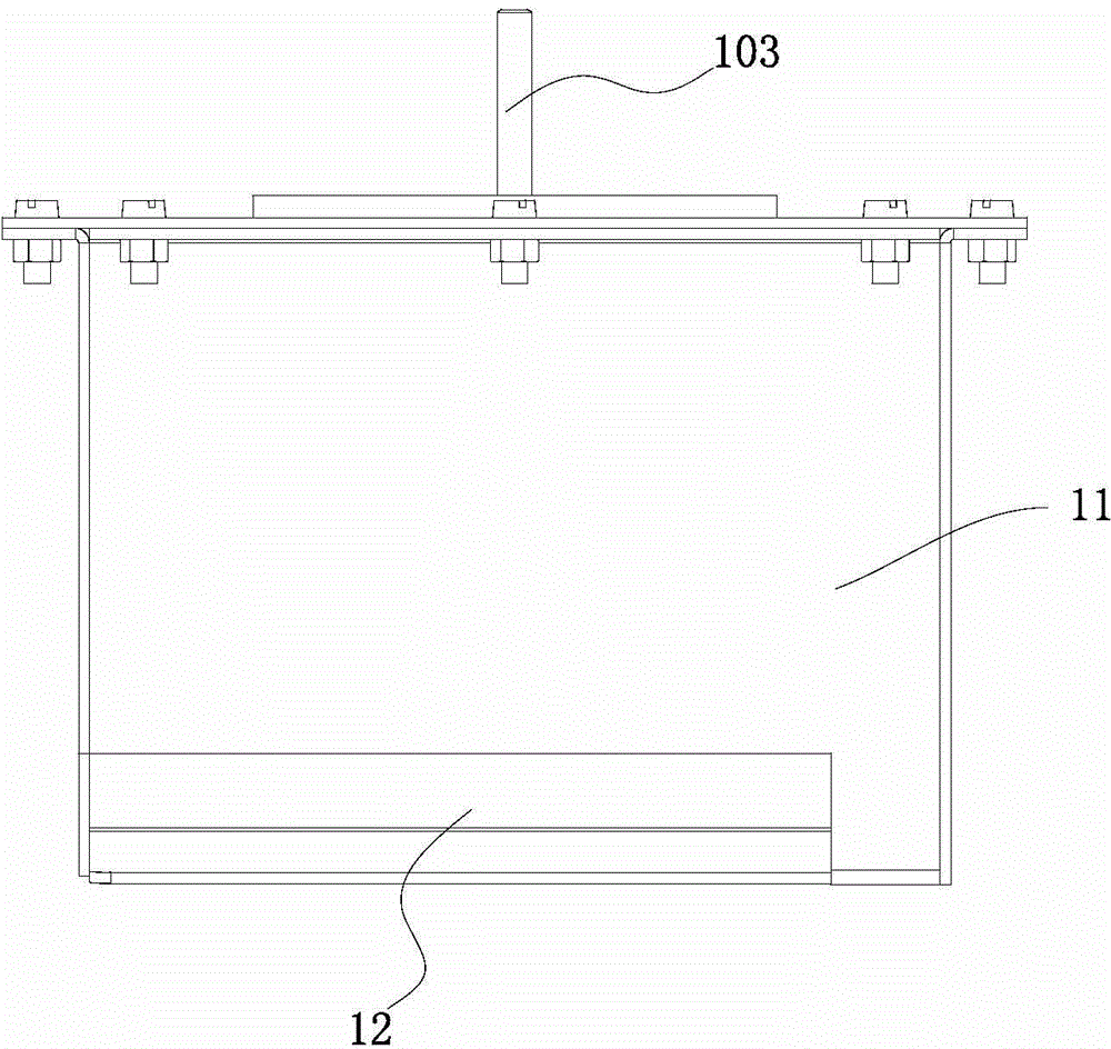
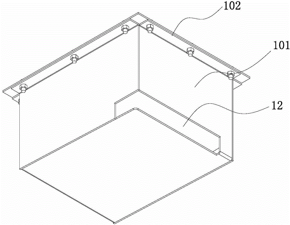
The invention discloses an oil-gas separation device and a compressor comprising the same. The oil-gas separation device comprises a shell, a baffle plate, a first filtering layer and a second filtering layer, wherein a cavity is defined in the shell, an inlet is formed in the lower portion of the shell, and an outlet is formed in the upper portion of the shell; the baffle plate is arranged in the cavity and located above the inlet; the first filtering layer is arranged above the baffle plate; the second filtering layer is arranged above the first filtering layer. According to the oil-gas separation device, the baffle plate is arranged in the shell, coolant gas and oil mist mixed gas entering the shell from the inlet passes through the baffle plate, thus the flow speed of the coolant gas and oil mist mixed gas can be decreased, liquid drops are formed on the wall surface of the baffle plate, the big liquid drops in the mixed gas are separated, the mixed gas is filtered through the first filtering layer and the second filtering layer, complete separation of coolant gas and oil mist is achieved finally, and the separation effect is good. The purity of the coolant gas flowing out of the outlet can be effectively improved.

Description

technical field [0001] The invention relates to the technical field of compressors, in particular to an oil-gas separation device and a compressor having the same. Background technique [0002] In the centrifugal compressor system, the filter with separate packing is mainly used, and the packing uses a general penetrating wire mesh, which has poor separation effect. During the operation, the oil mist will enter the impeller together with the refrigerant gas. The suction port will reduce the energy efficiency of the compressor and seriously damage the impeller. Contents of the invention [0003] The present invention aims to solve one of the above-mentioned technical problems at least to a certain extent. [0004] Therefore, an object of the present invention is to provide an oil-gas separation device with simple structure and good oil-gas separation effect. [0005] Another object of the present invention is to provide a compressor with the above-mentioned oil-gas separa...

Claims


Application Information

Patent Timeline
IPC IPC(8): F04D29/063F04D29/70
Inventor 王永茹志鹏李镇杉吴昕辜永刚
Owner CHONGQING MIDEA GENERAL REFRIGERATING EQUIP
Learn More