Eureka AIR delivers breakthrough ideas for toughest innovation challenges, trusted by R&D personnel around the world.

Energy-saving control device and method for data center air conditioning terminal

An air-conditioning terminal and data center technology, which is applied in the direction of refrigerators, refrigeration components, refrigeration and liquefaction, etc., can solve the problems of inability to coordinate the energy efficiency optimization of the water side and the air side, prone to local hot spots, and reduce system energy efficiency. The effect of decreasing the side temperature difference, prolonging the natural cooling time, and increasing the return water temperature

Inactive Publication Date: 2016-01-06
捷通智慧科技股份有限公司
View PDF9 Cites 14 Cited by
  • Summary
  • Abstract
  • Description
  • Claims
  • Application Information

AI Technical Summary

Problems solved by technology

[0007] The main shortcomings of the above two existing control methods are: ① only one temperature can be controlled, either only the return air temperature is controlled, or only the supply air temperature is controlled, and the influence of another temperature change on the controlled environment cannot be controlled. Local hotspots appear; ②The static pressure control loop adjusts the air volume and the temperature control loop adjusts the water volume. The two control loops are independent of each other. Temperature setting value or air supply temperature setting value), the static pressure setting value of the static pressure control loop is constant inside the program, and cannot be dynamically adjusted following the load change, resulting in excess cooling capacity and a drop in temperature difference during partial load operation, seriously reduce system energy efficiency

Method used

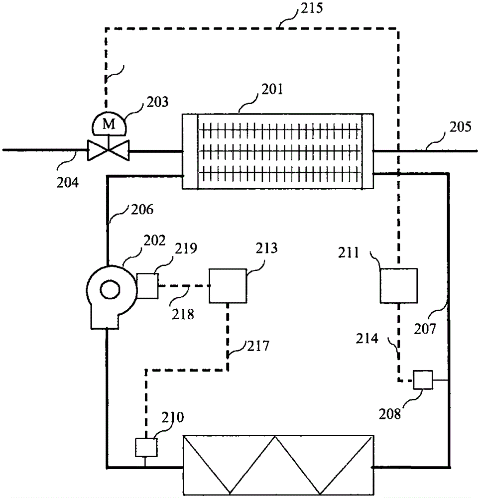
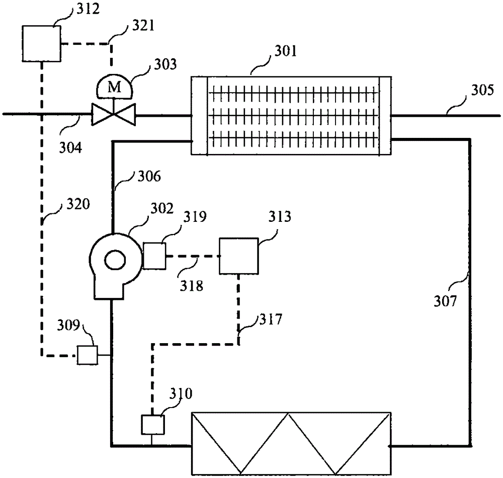

Image

  • Energy-saving control device and method for data center air conditioning terminal
  • Energy-saving control device and method for data center air conditioning terminal
  • Energy-saving control device and method for data center air conditioning terminal

Examples


Embodiment Construction

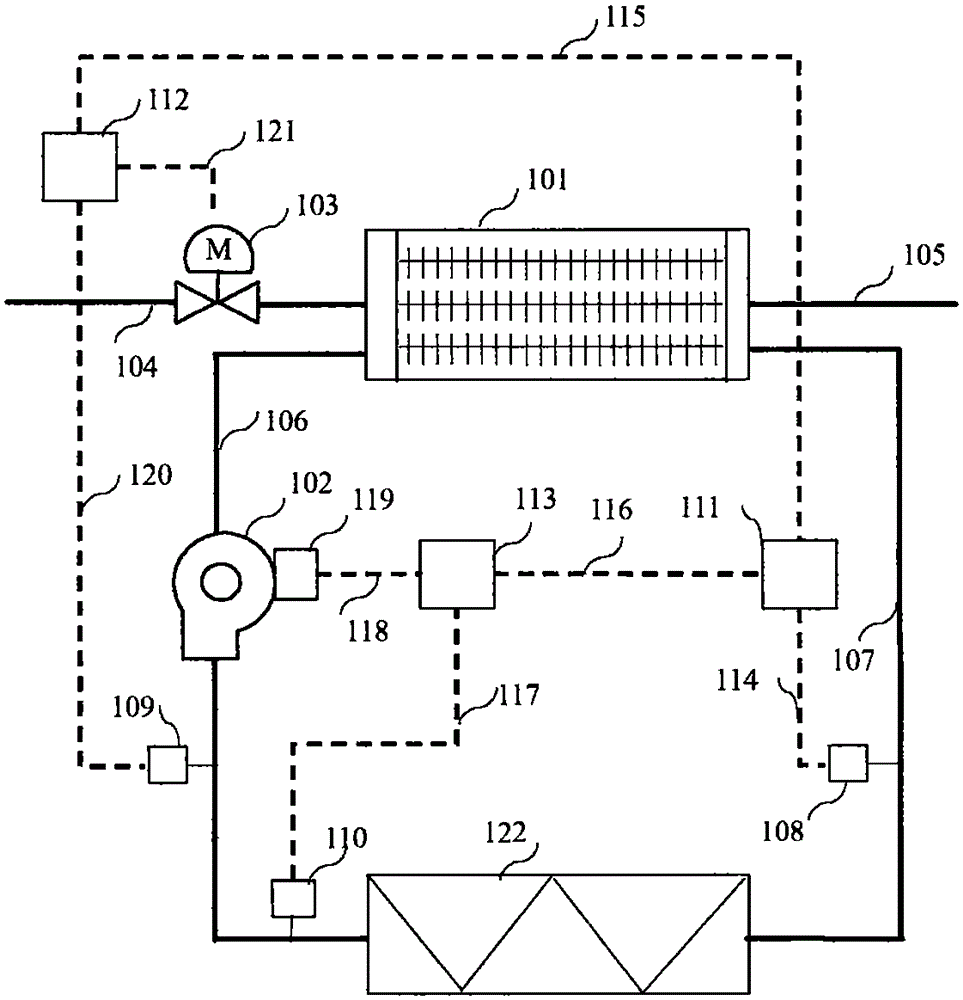
[0058] Such as figure 1 The energy-saving control device at the end of the air conditioner in the data center shown is applied to the cooling water coil 101, the fan 102, the regulating valve 103, the speed regulating actuator 119, the chilled water inlet pipeline, the chilled water outlet pipeline, the air supply channel and the return On the end structure of the data center air conditioner formed by the wind channel, the energy-saving control device of the present invention includes:

[0059] The air supply temperature sensor 109 is installed at the air outlet of the fan 102, and is used to obtain the air supply temperature value 120;

[0060] The air supply static pressure sensor 110 is installed between the air outlet of the fan 102 and the air inlet of the load equipment 122, and is used to obtain the static pressure value 117;

[0061] The return air temperature sensor 108 is installed at the air outlet of the load equipment 122 and is used to obtain the return air tem...


PUM


Abstract

The invention provides an energy-saving control device and method for a data center air conditioning terminal. The device and method are applied to a data center air conditioning terminal structure composed of a cold water coil pipe, a draught fan, a regulating valve, a speed regulation execution device, a chilled water inflow pipeline, a chilled water outflow pipeline, an air supply channel and an air return channel. The energy-saving control device comprises a supplied air temperature sensor, a supplied air static pressure sensor, a returned air temperature sensor, an optimization control module, a supplied air temperature control module, a static pressure module and the like. By the adoption of the device and method, the returned air temperature control accuracy can be improved, local hot spots are avoided, the supplied air is controlled in an environment-friendly safe section, the energy consumption of the draught fan of the data center air conditioning terminal can be saved as well, and the energy effect of a whole water cooling air conditioner system is improved.

Description

technical field [0001] The invention relates to energy-saving control of an air-conditioning system in a data center, in particular to an energy-saving control device and a control method at the end of an air-conditioning in a data center, which is generally called a "computer room air-conditioner". Background technique [0002] The air-conditioning end of the data center provides a thermal environment for the IT equipment in the computer room. In a typical data center energy consumption structure, the air conditioning system consumes about 40%, of which the data center air conditioning end accounts for about 10%. In a water-cooled air-conditioning system, the operating conditions of the air-conditioning end of the data center are not only related to the energy efficiency of the body, but also affect the energy consumption of the refrigeration station at the cold source end. [0003] The end of the air conditioner in the data center uses chilled water as the cooling medium ...

Claims


Application Information

Patent Timeline
Patent Type & Authority Applications(China)
IPC IPC(8): F25B49/00
Inventor 冉义兵肖峰
Owner 捷通智慧科技股份有限公司
Why Eureka
Eureka Blog
Learn More