A Half-bandwidth Matched Filter Realization Method for Frequency-Shifting Interference Identification

A matched filtering and frequency-shifting jamming technology, which is applied in half-bandwidth matched filtering to realize frequency-shifting jamming recognition and radar jamming false target recognition, can solve problems such as failure of frequency shift measurement method and affecting timeliness of false target recognition, and achieve easy The effect of engineering realization, fast speed and small amount of calculation

Active Publication Date: 2017-11-17
NAT UNIV OF DEFENSE TECH
View PDF5 Cites 0 Cited by
  • Summary
  • Abstract
  • Description
  • Claims
  • Application Information

AI Technical Summary

Problems solved by technology

The disadvantage of this method is that it assumes that the frequency-shifted interference signal has the same time width and bandwidth as the real target echo, and the jammer can completely change the time width and bandwidth of the forwarded interference signal by using DRFM technology, and control the center of the interference signal. Frequency, to ensure that it is the same as the target echo signal, so that the frequency shift measurement method is invalid
However, in practical applications, this method requires a lot of searching work for the best FRFT rotation angle, which affects the timeliness of false target recognition.
To sum up, it can be seen that the current frequency-shifting jamming false target recognition methods have their own shortcomings and shortcomings, and there is no effective frequency-shifting jamming false target recognition method applied to chirp radar

Method used


Image

  • A Half-bandwidth Matched Filter Realization Method for Frequency-Shifting Interference Identification
  • A Half-bandwidth Matched Filter Realization Method for Frequency-Shifting Interference Identification
  • A Half-bandwidth Matched Filter Realization Method for Frequency-Shifting Interference Identification

Examples


Embodiment Construction

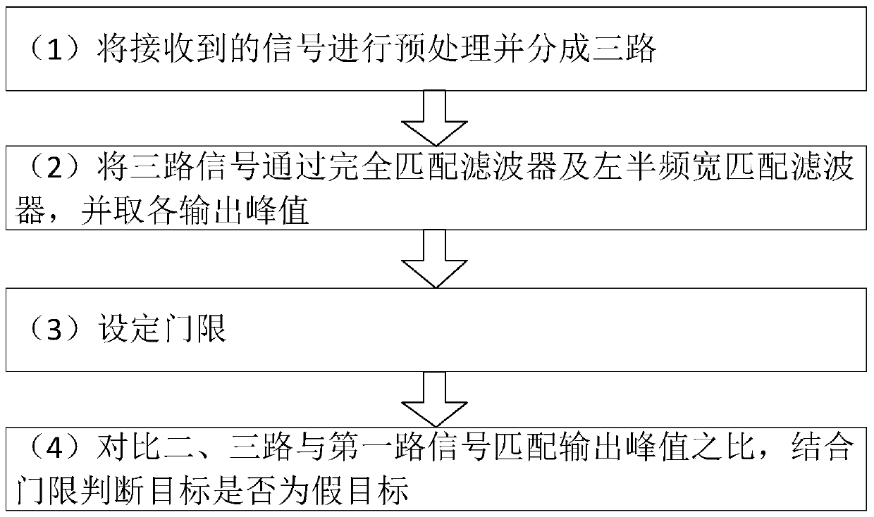
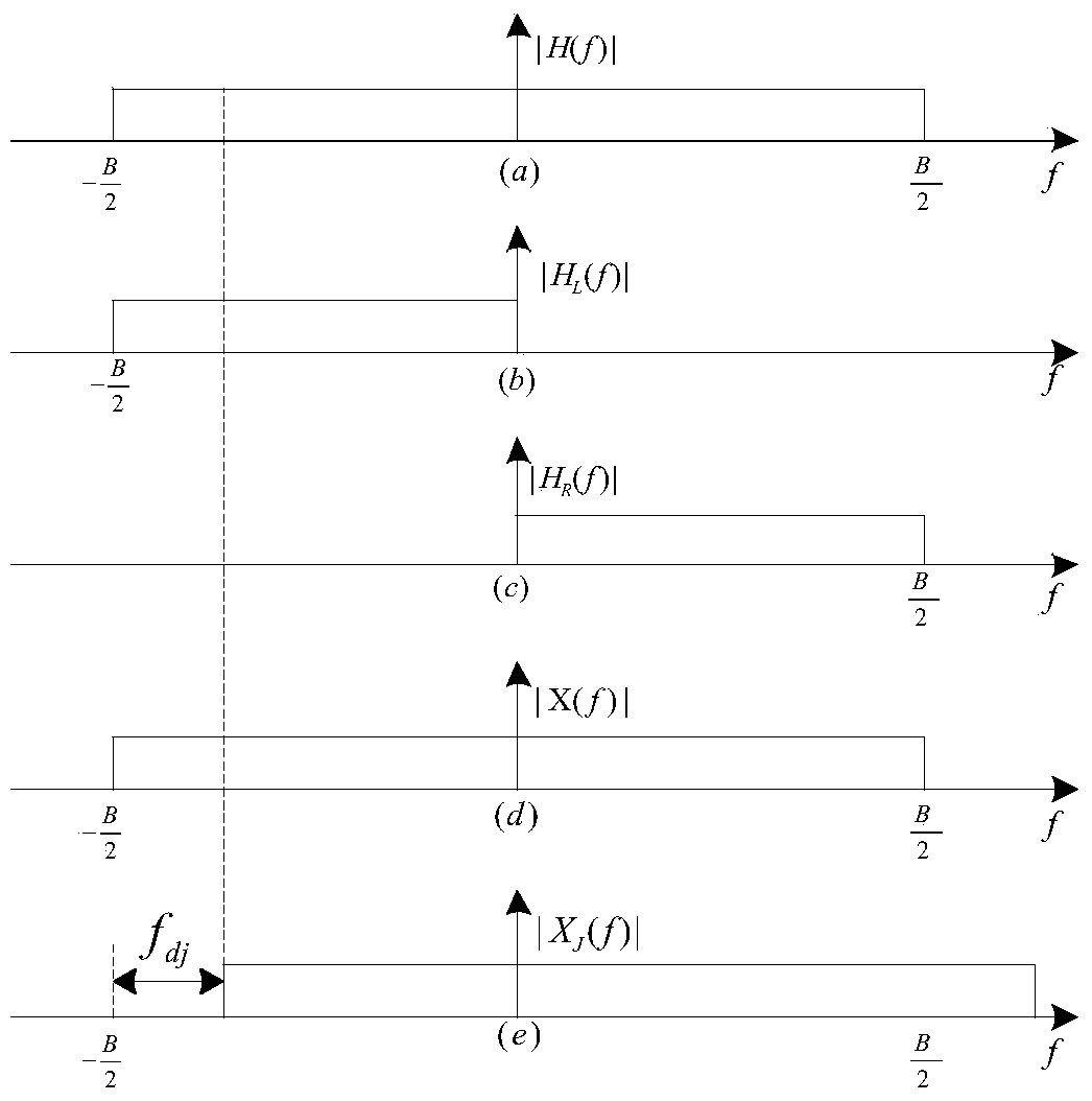
[0035] Figure 1 , Figure II The overall flow chart of the false target identification method and the design block diagram of the radar chirp signal frequency shift interference false target identification system are proposed for the present invention, and the embodiments of the present invention will be further described below in conjunction with the accompanying drawings.

[0036] The simulation experiment is based on a general-purpose computer, and is realized by using the Matlab simulation platform. The simulation parameters are set as follows: pulse width of radar transmission signal T=50us, bandwidth B=10MHz, carrier frequency f 0 =3000MHz, interference frequency shift f dj =-1Mhz, -3MHz, the leading distance of the false target generated at this time is 750m, 2250m.

[0037] A half-bandwidth matched filter of the present invention realizes a frequency shifting interference identification method, and the specific steps of the method are as follows:

[0038] Step 1: Fi...


PUM


Abstract

The invention discloses a method for realizing frequency shift interference identification through semi-bandwidth coupling filtering. The method has four major steps: 1, preprocessing signals received by a radar, and dividing the signals into three signals before matched filtering; 2, the three signals passing through a complete matched filter, and extracting each coupling filtering output voltage peak value; 3, setting a threshold; and 4, according to a matched output peak value ratio of a target under the condition of different coupling filters, and through combination with the set threshold, determining whether the target is a frequency shift interference false target. According to the invention, the disadvantage of frequency shift interference identification failure caused by a jammer in controlling the center frequency of interference signals by use of a conventional frequency shift measurement method is overcome, and detection identification of active leading false target interference can be realized; and there are fewer realization steps, the computational complexity is small, the requirement of the radar for real-time identification of multiple targets can be met, there are no additional requirements for a hardware system, and engineering realization is facilitated.

Description

technical field [0001] The invention belongs to the field of radar anti-jamming, relates to radar jamming false target recognition technology, and more specifically provides a half-band width matching filter to realize frequency-shifting jamming recognition method for linear frequency modulation radar. Background technique [0002] Linear frequency modulation signal (also known as chirp signal abroad) is a kind of pulse compression signal which is the earliest researched and most widely used. However, the chirp radar, which has many advantages such as large operating distance and high resolution, is extremely vulnerable to frequency shift interference. Immediately after detecting the signal, the frequency-shifting jamming technology will be used to generate long-distance realistic false targets in front of and behind itself, making it difficult for the radar to identify the real target. The target group will greatly consume radar resources. The major survival challenge fac...

Claims


Application Information

Patent Timeline
Patent Type & Authority Patents(China)
IPC IPC(8): G01S7/02
CPCG01S7/021
Inventor 冯德军甄晓鹏艾小锋肖顺平李永祯张静克
Owner NAT UNIV OF DEFENSE TECH
Why Eureka
Try Eureka