
Computed tomography metal artifact correction method and apparatus

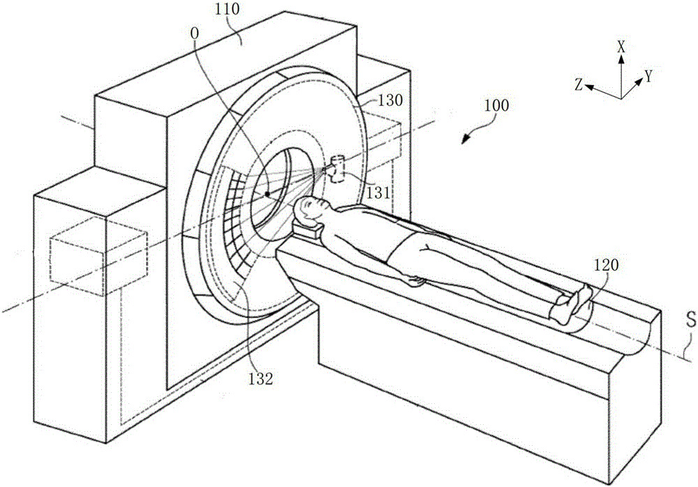
A technology of metal artifacts and correction methods, applied in computing, image enhancement, image analysis, etc., can solve the problems of image loss information, artifacts destroying tissue structure, etc.

Active Publication Date: 2016-01-06
SHANGHAI UNITED IMAGING HEALTHCARE
View PDF2 Cites 23 Cited by
  • Summary
  • Abstract
  • Description
  • Claims
  • Application Information

AI Technical Summary

Problems solved by technology

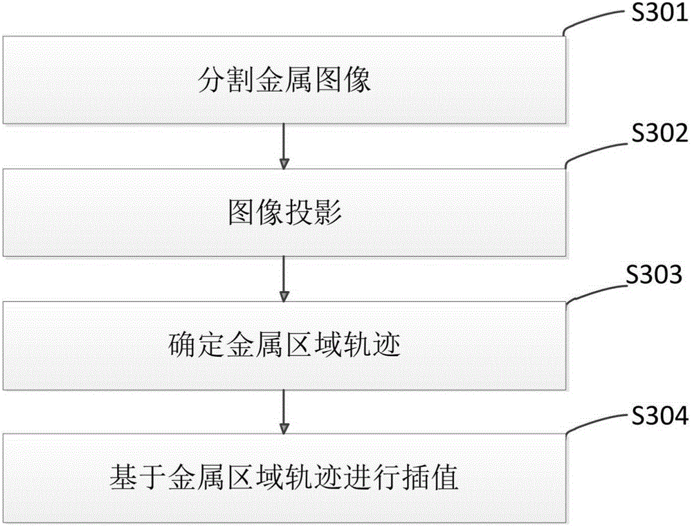
But in fact, because the original data of the area where the metal passes will contain some usable data, the complete replacement method of the interpolation method will cause the reconstructed image to lose the original information, and may also introduce new false information. Potential risks of affecting or destroying the organizational structure

Method used


Image

  • Computed tomography metal artifact correction method and apparatus
  • Computed tomography metal artifact correction method and apparatus
  • Computed tomography metal artifact correction method and apparatus

Examples


Embodiment 1

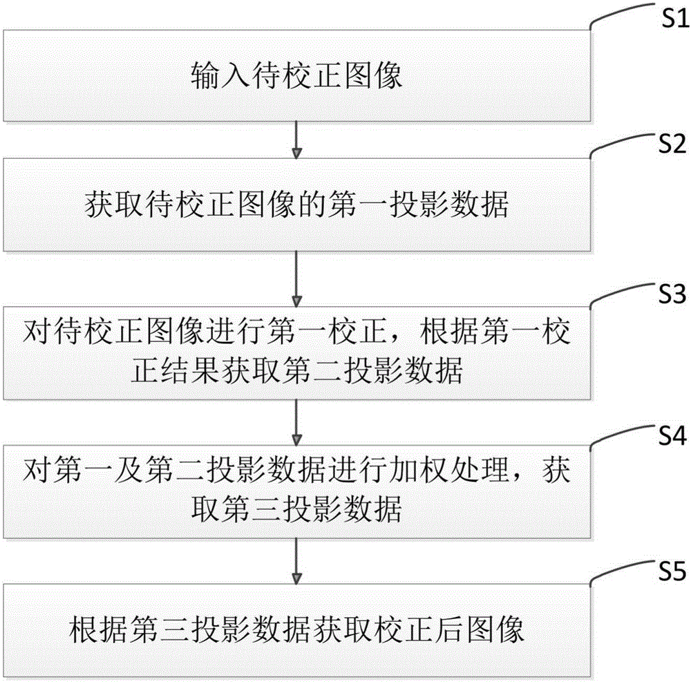
[0034] figure 2 A schematic flow chart of the metal artifact correction method of the first embodiment is shown. In this embodiment, step S1 is executed, and the image to be corrected is first input, and the image is obtained by the aforementioned computer tomography device. The input image can be a normal FoV (field of view, field of view) image in the image reconstruction process. If the normal FoV image does not cover the entire metal area, a full FoV image can also be used as the input, or the normal FoV image and the full The FoV image is also used as input. In addition, it can also input the image that has been filtered to remove noise during the reconstruction process to improve the quality of correction. This embodiment does not specifically limit the format, type, FoV size, and resolution of the input image. As long as the image has metal artifacts that need to be corrected, it can be used as the correction target of this embodiment.

[0035] Step S2 is executed to obt...

Embodiment 2

[0062] In order to obtain a better correction effect, in the process of obtaining the corrected image according to the third projection data, further correction may be performed according to the third projection data, that is, the second correction. According to the result of the second correction, other MAR methods can be further used, or the weighted correction method disclosed in the present invention can be re-corrected to obtain a corrected image.

[0063] E.g, Figure 5 The flowchart of the second embodiment of the present invention is shown. In this embodiment, a second correction is performed on the third projection data, and further operations such as weighting and information compensation are performed in the projection domain according to the second correction result to generate a corrected image.

[0064] Specifically, see Figure 5 As shown: first, input the image to be corrected (step S501) and perform a first correction operation on the image to be corrected (step S5...


PUM


Abstract

The present invention discloses a computed tomography metal artifact correction method. The method comprises: inputting a to-be-corrected image; acquiring first projection data of the to-be-corrected image; performing first correction on the to-be-corrected image and acquiring second projection data according to a result of the first correction; performing a weighting process on the first and second projection data to acquire third projection data; and obtaining a corrected image according to the third projection data. The present invention further discloses a metal artifact correction apparatus. According to the method and the apparatus provided by the present invention, artifacts can be further reduced and the quality of images can be improved on the premise of reserving available information of original images.

Description

【Technical Field】 [0001] The present invention relates to the technical field of computer tomography, and in particular to a method and device for correcting metal artifacts in computer tomography. 【Background technique】 [0002] Computed tomography is a technology that uses rays to scan specific parts of the human body at a certain thickness. According to the different absorption capabilities of different human tissues, the computer is used to reconstruct the tomographic image. [0003] In the process of computed tomography, the artifacts in the reconstructed image due to the metal contained in the scanned object are called metal artifacts. The presence of metal artifacts will reduce image quality and may affect the doctor's diagnosis. Therefore, in computed tomography imaging, Metal Artifact Reduction (MAR) is metal artifact correction. The solution is to remove the artifacts introduced due to the presence of metal and restore the tissue damaged or covered by the artifacts. [00...

Claims


Application Information

Patent Timeline
IPC IPC(8): G06T5/00G06T7/00
Inventor 王毅曹文静
Owner SHANGHAI UNITED IMAGING HEALTHCARE
Learn More