
Plasma processing apparatus and plasma processing method

A plasma and processing device technology, which is applied in the field of ion plasma processing devices, can solve problems such as time-consuming, and achieve the effect of improving the transition state

Active Publication Date: 2016-01-06
TOKYO ELECTRON LTD
View PDF8 Cites 0 Cited by
  • Summary
  • Abstract
  • Description
  • Claims
  • Application Information

AI Technical Summary

Problems solved by technology

[0008] However, there is a problem that in the case of switching from the first step to the second step, it takes time to enter the stabilization period of the plasma

Method used


Image

  • Plasma processing apparatus and plasma processing method
  • Plasma processing apparatus and plasma processing method
  • Plasma processing apparatus and plasma processing method

Examples


Embodiment Construction

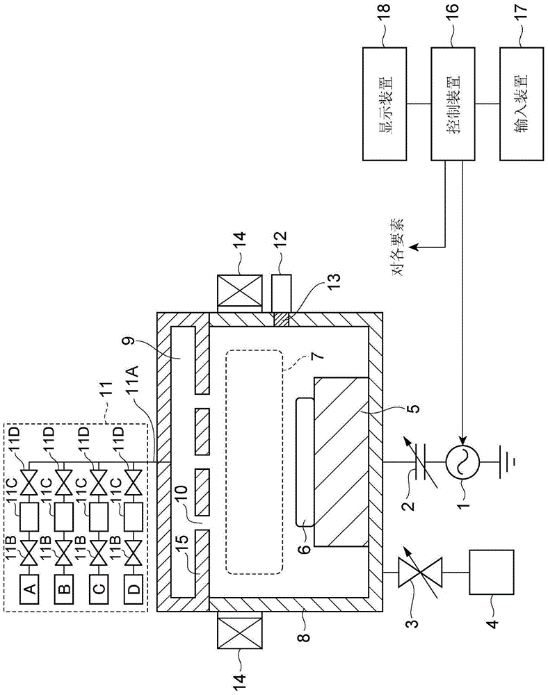
[0036]Next, the plasma processing apparatus and the plasma processing method according to the embodiment will be described. In addition, the same code|symbol is attached|subjected to the same element, and overlapping description is abbreviate|omitted.

[0037] figure 1 It is a figure which shows the structure of a plasma processing apparatus.

[0038] This plasma processing apparatus includes: a processing container 8; a gas supply system 11 that supplies gas into the processing container 8; a high-frequency wave generating source 1 that introduces high-frequency waves for plasma generation into the processing container 8; and an APC 3 with variable conductance. (Automatic pressure control valve: exhaust efficiency adjustment unit) that adjusts the exhaust efficiency of the gas in the processing container 8 . The APC3 is connected to an exhaust device 4 such as a turbomolecular pump, and the exhaust device 4 discharges the gas in the processing container 8 through the APC3....


PUM


Abstract

A controller disclosed herein drives, in a first step, a high frequency generating source at a first energy condition, and drives, in a second step, a high frequency generating source at a second energy condition. Prior to a switching time of the first step and the second step, the controller switches gas species supplied from the gas supply system into the processing container, and sets a gas flow rate in an initial period just after the switching to be larger than a gas flow rate in a stabilization period after lapse of the initial period.

Description

technical field [0001] Embodiments of the present invention relate to a plasma processing apparatus and a plasma processing method. Background technique [0002] Conventionally, a DRM (Dipole Ring Magnet: dipole ring magnet) type plasma processing apparatus is known as an apparatus for performing plasma processing such as film formation processing and etching processing on a semiconductor wafer. This DRM type plasma processing apparatus is provided with: a processing container which accommodates a semiconductor wafer; The plurality of cylindrical magnets are arranged vertically in pairs, and are connected to the rotation drive mechanism so as to be able to rotate synchronously. Each cylindrical magnet (sector magnet) rotates its magnetization direction once (reverses) when it rotates 180 degrees. Moreover, the DRM type plasma processing apparatus rotates a plurality of cylindrical magnets synchronously to apply a horizontal magnetic field in the processing container, and p...

Claims


Application Information

Patent Timeline
Patent Type & Authority Applications(China)
IPC IPC(8): H01J37/32H01L21/67
CPCH01J37/32174H01J37/3299H01J37/32449H01J37/32834H01J37/32082
Inventor 舟久保隆男芳贺博文狐塚慎一小澤亘坂本晃浩谷口直树辻本宏大野久美子
Owner TOKYO ELECTRON LTD
Learn More