Air blade and wet processing apparatus having the same

An air knife and the same technology, applied in the field of air knife and wet processing device with air knife, can solve the problems of water residue in silicon wafers, no fan, and increased debris rate, etc., to prevent uneven force, and to design airflow structure. reasonable effect

Inactive Publication Date: 2016-01-06
Jiangsu Boamax Technologies Group Co Ltd
View PDF6 Cites 1 Cited by
  • Summary
  • Abstract
  • Description
  • Claims
  • Application Information

AI Technical Summary

Problems solved by technology

[0004] The air knife structure used in the existing horizontal wet treatment equipment has the following problems: one is to use compressed air to dry, which needs to consume clean compressed air all the time, and the cost is high; the other is to use the air knife supplied by a general high-pressure fan , but due to the unreasonable structure of the existing air knife, there will still be a small amount of water remaining on the silicon wafer after the ai

Method used


Image

  • Air blade and wet processing apparatus having the same
  • Air blade and wet processing apparatus having the same
  • Air blade and wet processing apparatus having the same

Examples


Embodiment 1

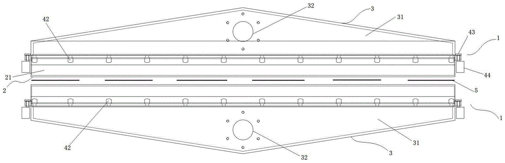
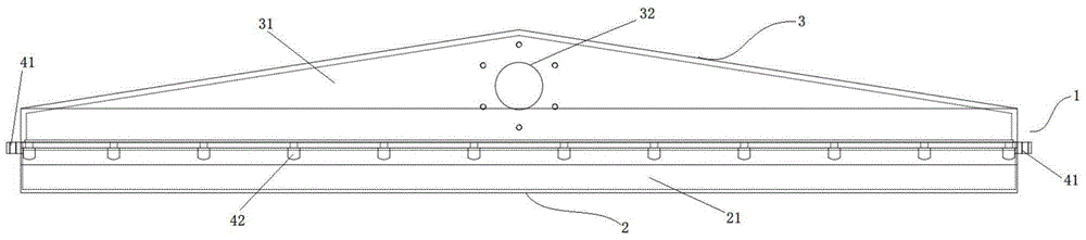
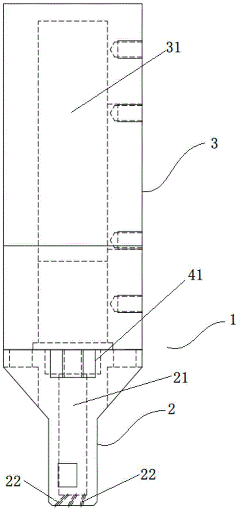
[0026] Example 1: figure 1 It is the front view of the air knife provided by the embodiment of the present invention, figure 2 It is the left view of the air knife provided by the embodiment of the present invention. It can be clearly seen from the figure that the air knife provided by this embodiment includes an air inlet part 3 and an air outlet part 2. The air inlet part 3 has an inlet The air inlet housing of the air chamber 31, the air outlet part 2 is an air outlet housing with an exhaust chamber 21 inside, and the air inlet chamber 31 of the air inlet housing communicates with the exhaust chamber 21 of the air outlet housing , the surface of the air inlet shell is provided with an air inlet 32, and the air outlet part 2 is provided with a plurality of exhaust channels 22, each exhaust channel 22 is inclined to the horizontal plane, and the sandwich between the exhaust channel 22 and the horizontal plane Angle is the inclination angle of the exhaust channel 22, and the...

Embodiment 2

[0041] Embodiment 2: Different from the air knife structure in Embodiment 1, the number of the exhaust channel groups is four, and the distance between adjacent exhaust channels 22 in the same exhaust channel group is kept constant. Under the premise that the corresponding exhaust channels 22 in the four exhaust channel groups overlap in the horizontal position, the silicon wafer will be blown more comprehensively and evenly. Similarly, according to the width of the air knife and two adjacent exhaust air The spacing of the channel groups can also increase or decrease the number of exhaust channel groups adaptively, without limiting the number of exhaust channel groups to three or four.

[0042] As a preferred arrangement, the included angles between the exhaust channel 22 and the end surface of the exhaust part 23 in the four exhaust channel groups from near to far from the inclined side are 40°, 53°, and 66° respectively. and 80°, but the present invention is not limited to s...


PUM

PropertyMeasurementUnit
Apertureaaaaaaaaaa

Abstract

The invention, which relates to the wet processing equipment field, discloses an air blade comprising an air inlet part and an air outlet part. The air inlet part and the air outlet part are communicated. The air inlet part is provided with an air intake. The air outlet part is provided with a plurality of air exhaust channels and each air exhaust channels is inclined towards the horizontal plane; and included angles between the air exhaust channels and the horizontal plane are inclined angles of the air exhaust channels, wherein the inclined angles of the air exhaust channels are not identical completely. Air is exhausted out of the air blade by the air exhaust channels. In addition, the invention also discloses a wet processing apparatus having the air blade. According to the air blade, the air intake pressure and the blast capacity demand are proper; airflow structure is designed reasonably; and the air exhaust can be carried out uniformly and the air is sprayed at different angles, so that a phenomenon of cracking of a silicon wafer or water stain existence due to uneven force application can be prevented.

Description

technical field [0001] The invention relates to the field of wet process equipment, in particular to an air knife and a wet processing device with the air knife. Background technique [0002] In the production process of solar cells, after chemical wet treatment and cleaning of solar cells, silicon wafers need to be dried for subsequent operations. [0003] In the traditional method, it is necessary to put silicon wafers into silicon wafer boxes and put them into a dryer for drying. The production efficiency is low and it is not suitable for horizontal wet processing. [0004] The air knife structure used in the existing horizontal wet treatment equipment has the following problems: one is to use compressed air to dry, which needs to consume clean compressed air all the time, and the cost is high; the other is to use the air knife supplied by a general high-pressure fan , but due to the unreasonable structure of the existing air knife, there will still be a small amount of...

Claims


Application Information

Patent Timeline
IPC IPC(8): H01L31/18F26B21/00
CPCF26B21/004H01L31/1804Y02E10/547Y02P70/50
Inventor 张淋程强强黄洪杰
Owner Jiangsu Boamax Technologies Group Co Ltd
Why Eureka
Try Eureka