
Unmanned plane capable of being automatically charged, charging system and charging method for unmanned plane

A charging system and automatic charging technology, applied in electromagnetic wave systems, secondary battery charging/discharging, battery circuit devices, etc., can solve problems such as inability to judge, increasing energy consumption and energy consumption of unmanned aerial vehicle round-trip flights

Active Publication Date: 2016-01-06
杨珊珊
View PDF9 Cites 63 Cited by
  • Summary
  • Abstract
  • Description
  • Claims
  • Application Information

AI Technical Summary

Problems solved by technology

However, there are still the following problems in the above-mentioned technical solution: there is a risk that the unmanned aerial vehicle will run out of power during the voyage to the charging pile
When the UAV stops working, it should be preferred to land it directly on the ground perpendicular to its current position. However, due to the uncertainty of the ground conditions, the operator cannot judge whether the ground corresponding to the current position is suitable. The place where the man-machine lands, so when the drone stops working, the operator often controls the drone to fly back to the control point and land near the control point, and then controls the drone to fly to the work place when the work task continues
Obviously, the above situation not only increases the energy consumption of the UAV's round-trip flight, but also causes unnecessary energy consumption for the UAV with insufficient battery life.

Method used


Image

  • Unmanned plane capable of being automatically charged, charging system and charging method for unmanned plane
  • Unmanned plane capable of being automatically charged, charging system and charging method for unmanned plane
  • Unmanned plane capable of being automatically charged, charging system and charging method for unmanned plane

Examples


Embodiment 1

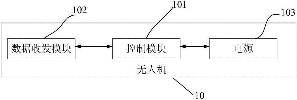
[0033] figure 1 It is a structural block diagram of the drone disclosed in this embodiment. Such as figure 1 As shown, in this embodiment, the UAV 10 mainly includes: a data transceiver module 102 for receiving control commands sent by the console (operator) and sending collected data, specifically, in this embodiment, the above-mentioned The data transceiver module is a wireless signal transceiver device; connected with the above-mentioned data transceiver module 102, for analyzing the data received by the above-mentioned data transceiver module 102 and controlling the operation of the unmanned aerial vehicle 10 according to the result of the analysis 101 Specifically, in this embodiment, the above-mentioned control module is a central processing unit; the power supply 103 connected to the above-mentioned control module 101 to supply the flying power of the UAV 10, and the power supply 103 can be recharged.

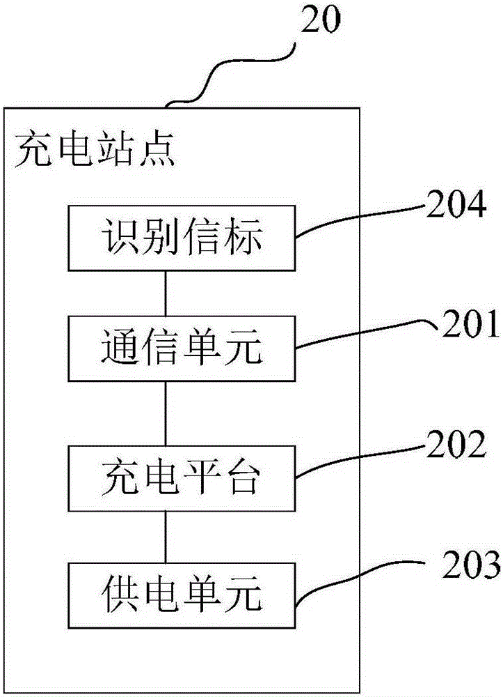
[0034] figure 2 It is a structural block diagram of the chargin...

Embodiment 2

[0058] The improvement of this embodiment relative to Embodiment 1 is that in this embodiment, in order to locate the charging stations more accurately, preferably, each charging station 20 includes a GPS unit, and the UAV 10 A GPS navigation module is also provided, so that when a suitable charging site 20 is selected, it is only necessary to send the GPS position information of the above-mentioned selected charging site 20 to the UAV 10, and the UAV 10 can then navigate in GPS. The module flies to the selected charging station 20 under the guidance of the module. In this case, the charging station 20 does not need to set an identification beacon, or in other words, at this time, the GPS information of the charging station 20 is equivalent to its identification beacon.

[0059] Other structures are similar to those in Embodiment 1 and will not be repeated here.

Embodiment 3

[0061] The difference between this embodiment and Embodiment 1 or Embodiment 2 is that in this embodiment, the above-mentioned UAV 10 is provided with a storage unit for storing the authentication code, and the above-mentioned charging station 20 is provided with a device that can verify whether the above-mentioned authentication code is Legitimate verification unit. In this way, a set of authorization authentication mechanism can be established between the drone 10 and the charging site 20, that is, a wireless handshake is required between the drone 10 and the above-mentioned selected charging site 20 to determine whether the above-mentioned drone 10 has obtained the above-mentioned The legal authorization certification of the charging station 20 ensures that the unmanned aerial vehicle approved by the operator can obtain the docking and charging service of the charging station, and prevents the unauthenticated unmanned aerial vehicle from occupying the resources of the operat...


PUM


Abstract

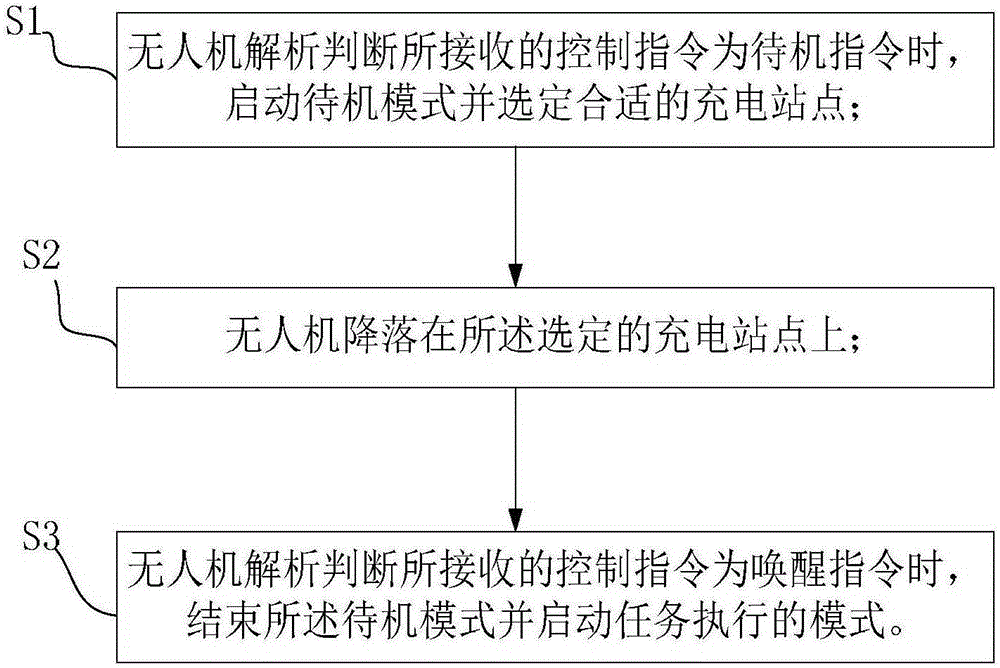
The invention mainly provides an unmanned plane capable of being automatically charged. The unmanned plane comprises a data transceiver module, a control module and a power supply, wherein the control module is used for controlling the unmanned plane to enter a standby mode and to automatically select a proper charging site to carry out landing and charging after analyzing a received control instruction into a standby instruction; and the control module is used for controlling the unmanned plane to convert into a task execution mode from the standby mode after analyzing the received control instruction into a wake-up instruction. In addition, the invention further provides an automatic charging system including the unmanned plane and an automatic charging method for the unmanned plane. By the unmanned plane, the charging system and the charging method, the standby interval of the unmanned plane can be fully utilized to carry out charging to supply energy; and a place for landing is provided for the standby state of the unmanned plane, so that the charging time of the unmanned plane is shortened; and energy consumption caused by a meaningless flight is avoided.

Description

technical field [0001] The present invention relates to the technical field of unmanned aerial vehicle application, more specifically, the present invention mainly relates to unmanned aerial vehicle charging technology. Background technique [0002] Unmanned aerial vehicle, unmanned aerial vehicle (UAV) for short, is a new concept of flying equipment in rapid development. Etc. By carrying multiple types of sensors, drones can realize real-time image transmission, detection of high-risk areas, etc., and at present, the scope of use of drones has been expanded to three major fields: military, scientific research, and civilian use, and has a wide range of applications. [0003] However, in order to make the drone have more functions, it is often necessary to carry various equipment on the drone. With the increase of equipment, the weight of the drone itself increases, and more power needs to be consumed to ensure the normal operation of the drone. Flying, but the battery powe...

Claims


Application Information

Patent Timeline
IPC IPC(8): H02J17/00H02J7/00G05D1/10H01M10/44
CPCY02E60/10
Inventor 杨珊珊
Owner 杨珊珊
Learn More