Rapid charging power supply system

A fast charging and power supply system technology, applied in charging stations, battery circuit devices, electric vehicle charging technology, etc., can solve problems such as low operating rate

Active Publication Date: 2016-01-06
INST FOR ENERGY APPL TECH
View PDF7 Cites 8 Cited by
  • Summary
  • Abstract
  • Description
  • Claims
  • Application Information

AI Technical Summary

Problems solved by technology

In addition, since electric vehicles are not yet fully popularized, the fixed fast charger according to Patent Document 2 is not frequently used, causing a problem of low operation rate

Method used


Image

  • Rapid charging power supply system
  • Rapid charging power supply system
  • Rapid charging power supply system

Examples


Embodiment 1

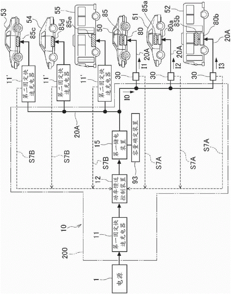
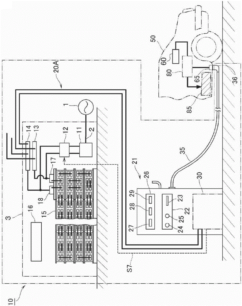
[0056] Figures 1 to 12 Embodiment 1 according to the present invention is shown. exist figure 2 In , reference numeral 1 denotes a commercial AC power supply as a power supply, and for example, a three-phase AC power supply is used as the AC power supply 1 . Power from the AC power source 1 is supplied into a building 3 through a power line 2 . Inside the building 3 , there are a first fixed quick charger 11 , a power feed control device 12 , a first power storage device 15 serving as a fixed power storage device, and other devices that make up the quick charging power supply system 10 . The input side of the first stationary fast charger 11 is connected to the power line 2 inside the building 3 . The first fixed quick charger 11 has a function of regulating three-phase AC power from the power line 2 to a predetermined voltage value and converting it into DC power. The output side of the first stationary charger 11 is connected to the first power storage device 15 throug...

Embodiment 2

[0097] Figure 13 According to Embodiment 2 of the present invention, the application of fast charging using electric energy obtained from renewable energy is shown. The difference between embodiment 2 and embodiment 1 lies in the power source used for fast charging and the difference corresponding to the rest of embodiment 1. Therefore, the same reference numerals as in Embodiment 1 denote corresponding parts, and thus descriptions about the corresponding parts are omitted. This applies to other embodiments to be described below.

Embodiment 3

[0101] Figures 14 to 15 Embodiment 3 according to the present invention is shown. The difference between Embodiment 3 and Embodiment 1 is that only the power switching device 11 m exists or does not exist in the first fixed fast charger 11 . In Embodiment 3, for charging the vehicles 53 to 55 which are the second electric moving bodies not equipped with the fast charging control device, by using only the first fixed fast charger 11 without applying the first power storage device 15 or the second Two fixed fast chargers 11' are capable of fast charging.

[0102] Such as Figure 14 As shown in , the power switching device 11m is connected to the output side of the power switching device 11m. Such as Figure 15 As shown in , in Embodiment 3, the power switching device 11m is integrated with the first fixed fast charger 11 . The power conversion switch 11m is composed of a first fixed contact a, a second fixed contact b and a movable contact c. Such as Figure 15 As shown ...


PUM


Abstract

A rapid charging power supply system capable of rapid charging, using a single system, both an electric moving body having a rapid-charging control means equipped therein and an electric moving body that does not have a rapid-charging control means equipped therein is provided. The system comprises: a first stationary rapid charger 11 capable of controlling electric power supplied from a power supply to be DC power having a voltage and a current optimum for charging various types of electric storage means, including charging of on-vehicle electric storage means 85c to 85e of at least second electric moving bodies 53 to 55; a stationary electric storage means 15 capable of storing the DC power which is charged by the first stationary rapid charger 11 and is supplied to first electric moving bodies 50 to 52 or to the second electric moving bodies 53 to 55; a second stationary rapid charger 11' capable of controlling the DC power from the stationary electric storage means 15 to be DC power having a voltage and a current optimum for rapid charging of the on-vehicle electric storage means 85c to 85e equipped in the second electric moving bodies 53 to 55; and a power feeding control means 12 for discontinuing power feeding from the first stationary rapid charger 11 to the stationary electric storage means 15, during the charging of the on-vehicle electric storage means 85 of the first electric moving bodies 50 to 52 with the DC power output from the stationary electric storage means 15, and during the charging of the on-vehicle electric storage means 53c to 53e of the second electric moving bodies 53 to 55 with the DC power output from the stationary electric storage means 15 which is performed through the second stationary rapid charger 11'.

Description

technical field [0001] The present invention relates to a quick charging power supply system capable of quickly charging an electric moving body such as a vehicle, and more particularly, the present invention relates to a quick charging capable of quickly charging two electric moving bodies of different charging methods simultaneously using a single system Power system. Background technique [0002] Although electric vehicles are excellent from an environmental point of view because they do not emit exhaust gas, electric vehicles have a problem in that they require a relatively long charging time. In order to shorten the charging time, it is necessary to supply a large amount of electric power to electric vehicles in a short period of time, and for areas where only low-voltage power lines are laid, it is necessary to increase the power receiving capacity of power facilities. Therefore, there is a known technology to rectify commercial alternating current (AC) power to store...

Claims


Application Information

Patent Timeline
Patent Type & Authority Applications(China)
IPC IPC(8): B60L11/18
CPCB60L3/00B60L2200/10B60L2200/18B60L2200/26B60L2200/36B60L2200/42Y02T90/14Y04S30/14Y02P90/60B60L53/16B60L53/65B60L53/11B60L53/305B60L53/51B60L53/52B60L53/54B60L53/53H02J7/342B60L53/67B60L58/26B60L58/18H02J2310/48Y02T10/70Y02T10/7072Y02T90/12Y02T90/16Y02T90/167H02J7/0013H02J3/32
Inventor 菅野富男
Owner INST FOR ENERGY APPL TECH
Why Eureka
Try Eureka