Slot feature side milling machining tool path generating method

A groove feature and tool path technology, applied in metal processing, metal processing equipment, metal processing machine parts, etc., can solve the problems of sudden changes in cutting direction, affecting processing quality, machine tool vibration, etc.

Active Publication Date: 2016-01-13
CHENGDU AIRCRAFT INDUSTRY GROUP
View PDF5 Cites 19 Cited by
  • Summary
  • Abstract
  • Description
  • Claims
  • Application Information

AI Technical Summary

Problems solved by technology

[0007] The purpose of the present invention is to solve the problems that the machine tool is subjected to uneven force and the cutting direction changes suddenly during the slot feature side milling process, which causes the machine tool to vibrate, the tool wear is intensified, and the processing quality is seriously affected, and a slot feature side milling process is proposed. Tool path generation method, which makes the tool load stable and the curvature of the tool path changes uniformly, considering the dual constraints of cutting force and machine tool dynamics

Method used


Image

  • Slot feature side milling machining tool path generating method
  • Slot feature side milling machining tool path generating method
  • Slot feature side milling machining tool path generating method

Examples


Embodiment Construction

[0045] The present invention will be further described below in conjunction with the accompanying drawings and embodiments.

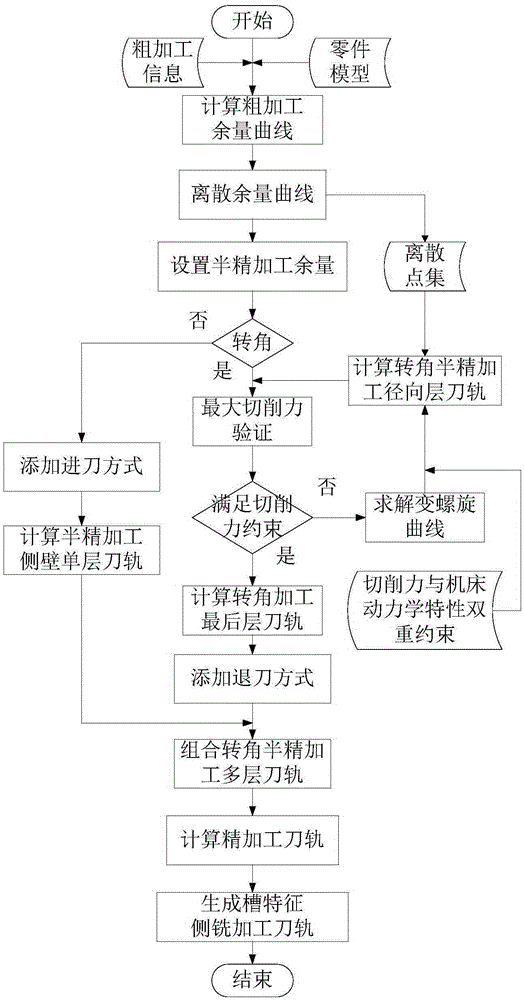
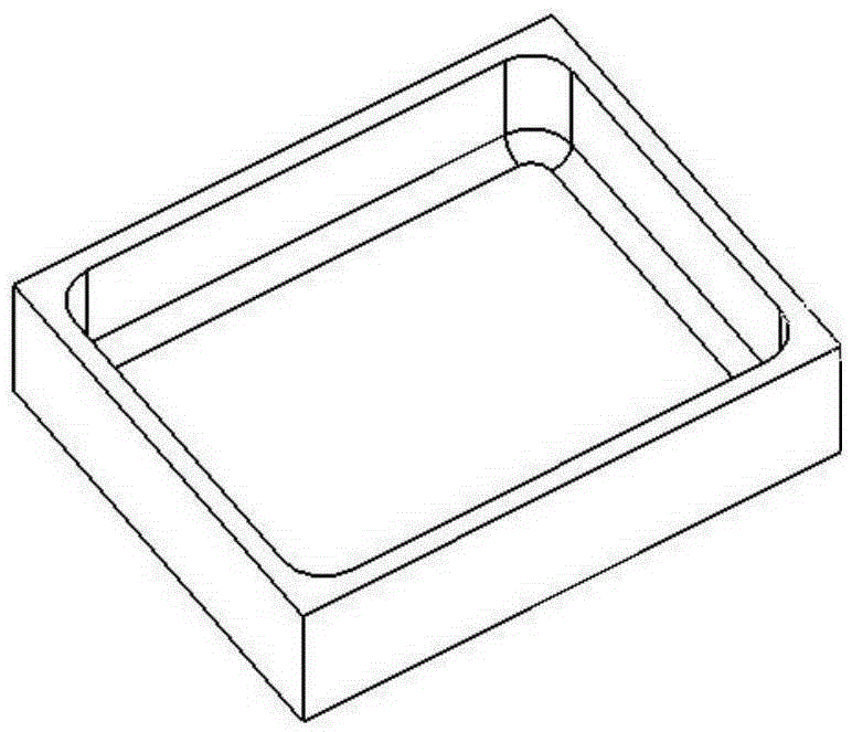
[0046] The tool path generation method proposed by the invention is based on rough machining. by figure 2 The typical groove characteristics shown in the figure illustrate the process flow of a method for generating a groove characteristic side milling tool path proposed by the present invention. The groove characteristic size is 200mm×160mm, and a Φ12mm tool is selected for processing. The groove characteristic side milling tool path generation process is as follows:

[0047] Step 1, according to the groove feature rough machining information and the part model, obtain the material allowance μ to be processed, and calculate the rough machining allowance curve;

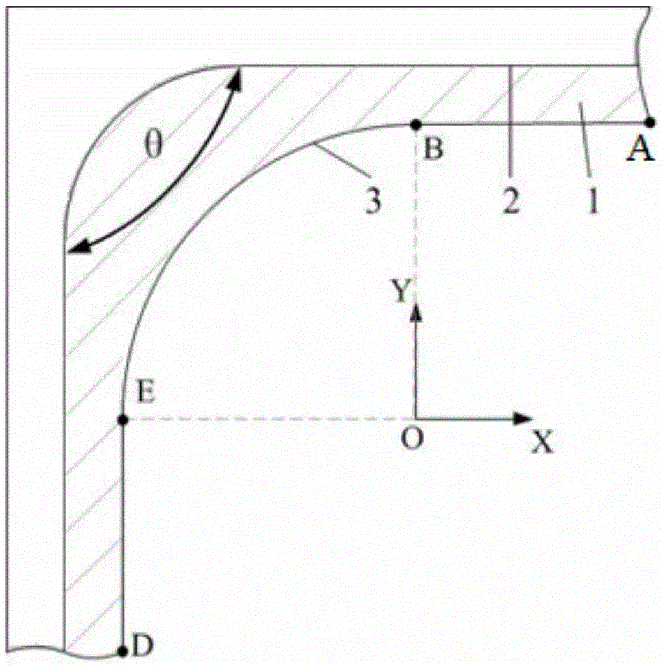
[0048] First establish a local coordinate system, take the center of the margin arc at the corner as the coordinate origin, and take the direction of the margin line equation on both sides of...


PUM


Abstract

The invention provides a slot feature side milling machining tool path generating method. According to the method, the double restraints of cutting force and the machine tool dynamics characteristic are taken into comprehensive consideration. The corner is machined through a multi-layer tool path based on circulation milling, and the side wall is machined with a sing-layer tool path. The tool contact angle is limited in the machining process, and the cutting force is restrained. By means of a variable helical curve, the change of the curvature of the tool path curve meets the machine tool dynamics characteristic. The cutting force and vibration in the machining process can be effectively reduced through the slot feature side milling machining tool path second-order continuity and guide rail curvature continuous changes, and the component machining quality, efficiency and yield are improved.

Description

technical field [0001] The invention relates to a numerical control machining method for mechanical parts, in particular to a side milling method for groove features, in particular to a tool path generation method for side milling groove features with the same tool. Background technique [0002] Aircraft structural parts are an important part of the aircraft body skeleton and aerodynamic shape. There are often a large number of slot features in the design to meet the lightweight design requirements of the aircraft. The machining accuracy of the inner shape of the groove feature is high, the roughness requirement is generally 3.2 μm, and the key part can reach 1.6 μm or 0.8 μm. In the process of side milling corners, the cutting direction changes suddenly, and even sharp points of the tool path appear, resulting in sharp changes in cutting width and cutting force, resulting in intensified tool vibration, chattering of the machine tool, and affecting the processing quality of ...

Claims


Application Information

Patent Timeline
IPC IPC(8): B23C3/34G05B19/19B23Q15/02
Inventor 隋少春高鑫牟文平马飞
Owner CHENGDU AIRCRAFT INDUSTRY GROUP
Why Eureka
Try Eureka