Metal surface uniform film-removing device based on self-compensation

A metal surface, self-compensating technology, applied in the direction of grinding drive devices, metal processing equipment, grinding machine tool parts, etc., can solve the problems of high manual adjustment experience requirements, heavy workload of workers, and affecting production efficiency, etc., to achieve Improve production efficiency and economic benefits, simple structure, high production efficiency

Inactive Publication Date: 2016-01-13
WUHAN UNIV OF SCI & TECH
View PDF5 Cites 6 Cited by
  • Summary
  • Abstract
  • Description
  • Claims
  • Application Information

AI Technical Summary

Problems solved by technology

[0003] To sum up, the existing film removal device has the following problems: the film removal is uneven, the wear gap of the wire brush needs to be adjusted manually, the workload of the workers is heavy, and the manual adjustment experience is relatively high, which affects the production efficiency

Method used


Image

  • Metal surface uniform film-removing device based on self-compensation
  • Metal surface uniform film-removing device based on self-compensation
  • Metal surface uniform film-removing device based on self-compensation

Examples


Embodiment 1

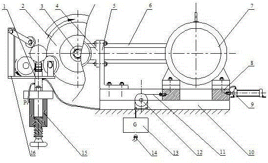
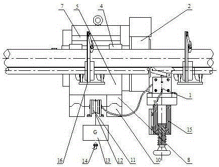
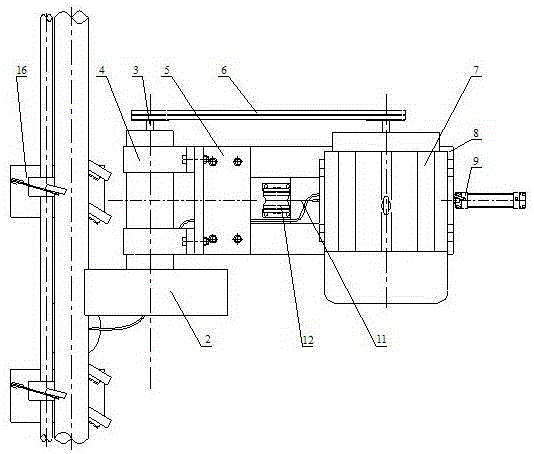
[0037] A device based on self-compensation for uniform film removal on metal surfaces. like figure 1 , figure 2 and image 3 As shown, the device includes stroke valve 1, wire brush 2, transmission shaft 3, belt 6, motor 7, guide rail pair 8, cylinder 9, guide rail 10, steel wire rope 11, fixed pulley 12, weight block 13, alarm switch 14, Height regulator 15 and indicator light 18.

[0038] like figure 1 , figure 2 and image 3 As shown, the guide rail 10 is horizontally fixed on the frame, and the guide rail pair 8 is movably installed on the guide rail 10 . Motor 7 is fixed on the upper plane of guide rail pair 8 right-hand sides, transmission shaft bearing seat 4 is installed on the upper plane of guide rail pair 8 left ends by bearing seat holder 5, and power transmission shaft 3 is installed in the transmission shaft bearing seat 4. Wire brush 2 is installed on one end of transmission shaft 3, and the belt pulley that is installed in transmission shaft 3 other en...

Embodiment 2

[0049] A self-compensation-based uniform film removal device for metal surfaces. Except the following technical parameters, all the other are the same as in Example 1:

[0050] The distance between the initial position of the weight block 13 and the alarm switch 14 is 47-50 mm.

[0051] The included angle between the axis of the fixed wheel 22 and the axis of the driving wheel 23 is 30-45°, and the included angle between the axis of the driven wheel 24 and the axis of the driving wheel 23 is 25-35°.

[0052] The distance between the roller of the stroke valve 1 and the front side of the wire brush 2 is 35-50 mm.

[0053] The cylinder stroke of the cylinder 9 is 70-90 mm.

[0054] The working process of this specific embodiment is: install the rod to be removed on the transmission frame 16, adjust the height adjuster 15 so that the roller of the stroke valve 1 is just pressed down by the rod to be removed, so that the valve core of the stroke valve 1 is pressed down by the ro...


PUM


Abstract

The invention relates to a metal surface uniform film-removing device based on self-compensation. According to the technical scheme, a motor (7) drives a steel wire brush (2) to rotate through a belt (6); and a heavy object block (13) is connected with a guide rail pair (8) through a fixed pulley (12) by virtue of a steel wire rope. An air cylinder (9) is hinged with the right end surface of the guide rail pair (8); height of a stroke valve (1) is regulated by virtue of a height regulator (15), so that a rod to be subjected to film removal can press down a roller wheel of the stroke valve (1), and a valve element of the stroke valve (1) reverses. During the film removal, the steel wire brush (2) is in constant-force contact with the rod to be subjected to film removal under the gravity action of the heavy object block (13), so that self-compensation uniform film removal is realized. When the film removal is completed, the air cylinder (9) pulls the guide rail pair (8) to move rightwards to wait for a rod to be subjected to film removal. When the steel wire brush (2) reaches use limit, the heavy object block (13) is descended to a maximum position for triggering an alarm switch (14), so that an indicator lamp (18) is turned on to remind a worker to replace the steel wire brush (2). The metal surface uniform film-removing device based on self-compensation has the characteristics of low cost, a simple structure, uniform film removal, automatic abrasion gap compensation and high production efficiency.

Description

technical field [0001] The invention belongs to the technical field of metal surface film removal. In particular, it relates to a self-compensation-based uniform film removal device for metal surfaces. Background technique [0002] Bimetal composite material is a new type of technological material that integrates the characteristics of two metals. It is a metal composite material that utilizes the respective advantages of the two metals, such as copper-clad aluminum bimetal. The metal has light weight, excellent electrical conductivity, It has the characteristics of saving copper resources and low production cost. In order to make the two metals form an interatomic metallurgical bond at the interface, the oxide film on the surface must be removed. Although the existing film removal device can remove the surface oxide film, as time goes by, the wire brush wears and consumes, and different batches of rods There are differences in the film removal effect of different material...

Claims


Application Information

Patent Timeline
Patent Type & Authority Applications(China)
IPC IPC(8): B24B27/033B24B27/00B24B47/25
CPCB24B27/0069B24B27/033B24B47/25
Inventor 胡光武曾良才涂福泉杜辉毛阳
Owner WUHAN UNIV OF SCI & TECH
Why Eureka
Try Eureka