
Tensioner for parallel steel strand stay cables and construction method thereof

A cable-stayed cable tensioner and parallel steel strand technology, applied in bridge parts, erection/assembly of bridges, bridges, etc., can solve the problems of inconvenient construction operation, increased construction difficulty, impossible installation, etc. The cable effect is obvious, the construction efficiency is improved, and the operation is convenient.

Active Publication Date: 2016-01-13
LIUZHOU OVM ENG
View PDF9 Cites 0 Cited by
  • Summary
  • Abstract
  • Description
  • Claims
  • Application Information

AI Technical Summary

Problems solved by technology

[0003] However, the parallel steel strand stay cable is composed of multiple steel strand group anchor systems, and an index requirement is that no twisting phenomenon is allowed in each strand unit; another feature of the steel strand stay cable is good resistance Wind resistance, this characteristic is related to the diameter of the outer sheath tube of the steel strand. Reducing the outer diameter of the outer sheath tube as much as possible is an important indicator for the wind resistance design of the stay cable, but too small a diameter puts forward strict requirements for on-site installation and construction. The difficulty of construction increases, and even the installation becomes impossible;
[0004] How to ensure the cable installation of each strand unit of the steel strand stay cable is one of the key points in construction: overcoming the geometric gap between the strands during the construction process is one of the technical guarantees to ensure the smooth installation of the steel strands, and parallel steel strands The tensioner of the strand cable can be an effective special tool for this construction process, while the steel strand tensioner on the market is arranged according to the polygonal shape of the steel strand, and after tightening, it becomes a polygonal cross-section and fails to achieve a circular shape. The requirement for the smallest cross-sectional area, that is, the space cannot be vacated, and the construction operation is extremely inconvenient. Therefore, a special tool for circular tightening and restraint of parallel steel strand loose cables has been developed, which reduces the difficulty of construction. Cable device is a technical problem that those skilled in the art are eager to solve

Method used


Image

  • Tensioner for parallel steel strand stay cables and construction method thereof
  • Tensioner for parallel steel strand stay cables and construction method thereof
  • Tensioner for parallel steel strand stay cables and construction method thereof

Examples


Embodiment 1

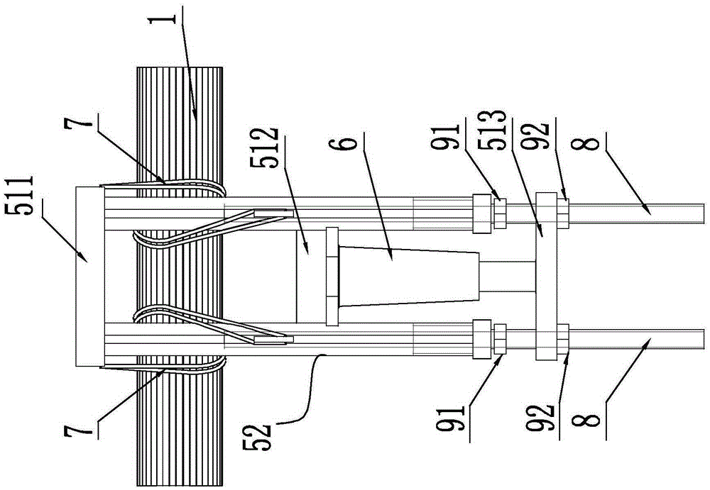
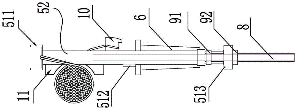
[0036] A cable tensioner for parallel steel strands, such as figure 2 , image 3 As shown, the tensioner includes: a frame 5, a jack 6, an adjusting jack 8 and a matching flexible band 7;

[0037] The frame 5 includes three beams of fixed cross-connection I 511, fixed cross-connection II 512 and movable cross-connection 513, two vertical beams with grooves 52, two special-shaped steel structures 11 and two reaction hooks 10; fixed cross-connection I 511 Installed on the top of the two vertical beams with grooves, the fixed cross-link II 512 is installed between the two vertical beams with grooves 52 and fixedly connected with them to make it a whole, and the two adjusting push rods 8 pass through the movable cross-links 513 and installed respectively In the grooves of the two vertical beams with grooves 52 of the frame and can move freely in the grooves of the vertical beams with grooves 52, the adjusting push rod 8 has external threads and is fixed on a certain position on ...

Embodiment 2

[0042] A method for tight cable construction, which is a method for using a parallel steel strand cable tensioner described in Embodiment 1 for tight cable construction, and its construction steps are:

[0043] A. Initial tension:

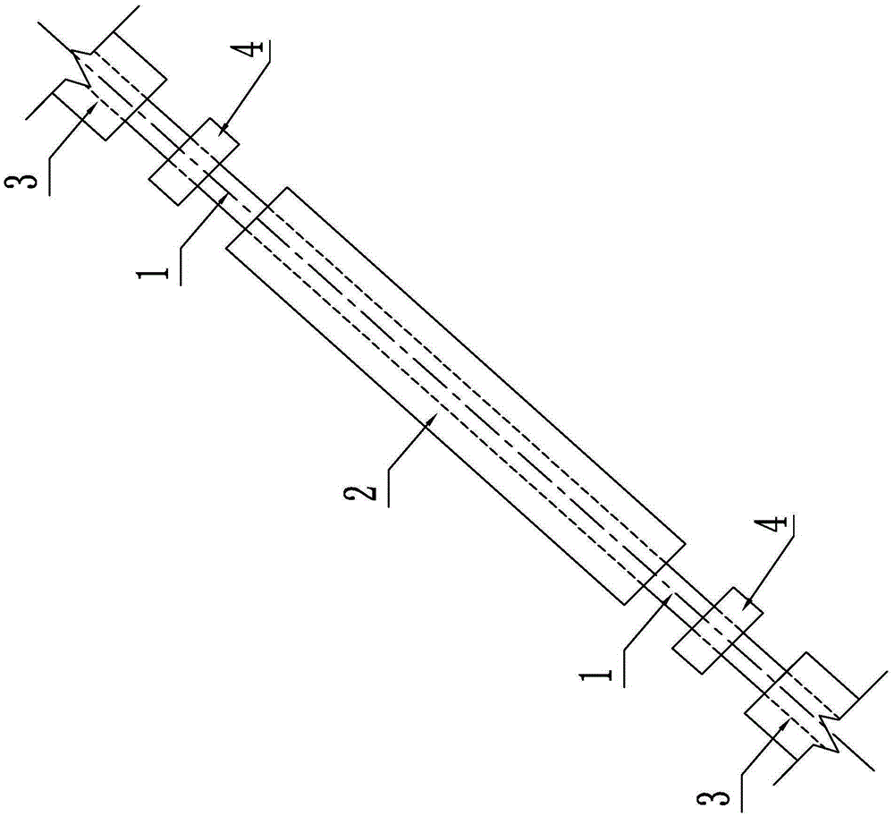
[0044] Install the stay cable outer sheath round tube 2 and the stay cable pre-buried tube 3, and install the steel strand unit 1 in the sheath tube. When the space in the round tube is not enough to install the subsequent steel strand unit, install the cable tensioner 4 Initial tensioning of installed strand units;

[0045] B, shelve the tensioner 4 on the outer surface of the steel strand body unit 1 (see Figure 1-Figure 3 ):

[0046] Among them, the inner arc surface of the special-shaped steel structure 11 is matched with the outer circular surface of the steel strand body unit 1, and one end of the flexible band 7 is connected to the horizontal connecting plate of the frame, and the other end is wound on the installed steel strand body unit...


PUM


Abstract

The invention discloses a tensioner for parallel steel strand stay cables. The tensioner comprises a rack, a jack, adjusting ejector rods and flexible straps matched with the adjusting ejector rods for use. The rack comprises a fixed cross beam I, a fixed cross beam II, movable cross beams, two vertical beams with grooves, two special-shaped steel structures and two counter-force hooks. The fixed cross beam I is mounted on the tops of the two vertical beams with the grooves, and the fixed cross beam II is mounted between the two vertical beams with the grooves and is fixedly connected with the vertical beams with the grooves to form a whole. The two adjusting ejector rods penetrate through the movable cross beams to be mounted in the grooves of the two vertical beams with the grooves of the rack respectively and can move freely in the grooves of the vertical beams with the grooves, the adjusting ejector rods are provided with external threads, and the external threads are fixed to certain positions of the adjusting ejector rods through nuts II. The movable cross beams are mounted on the adjusting ejector rods and can move up and down along the adjusting ejector rods and be fixed to certain positions of the adjusting ejector rods through nuts II. The bottom of the jack is mounted on the fixed cross beam II, and the piston end of the jack is fixedly connected with the movable cross beams. The tensioner is simple in structure, and the parallel steel strand stay cables can be subjected to round tightening constraint.

Description

technical field [0001] The invention relates to a bridge construction machine tool and a construction method thereof, in particular to a cable tensioner and a construction method for parallel steel strand stay cables. Background technique [0002] In bridge construction, a cable-stayed bridge is a bridge with cables as a supporting system, and steel strands are used as a cable system for this system. A construction feature of steel strand cable-stayed cables is the construction method of fragmentation It can complete the installation of large-tonnage cable-stayed cables without using large-scale construction equipment, making it an important selection indicator for the bridge industry. Because it has insurmountable technical advantages of other cable systems, the steel strand cable-stayed cable system is increasingly used Widely used in bridge structures. [0003] However, the parallel steel strand stay cable is composed of multiple steel strand group anchor systems, and an...

Claims


Application Information

Patent Timeline
Patent Type & Authority Applications(China)
IPC IPC(8): E01D19/16E01D21/00
Inventor 韦福堂吕兵张志红陈宗泽张国强简铃方
Owner LIUZHOU OVM ENG
Learn More