Electromagnetic metering ball valve

A ball valve, electromagnetic technology, applied in the valve details, valve device, valve operation/release device and other directions, to achieve the effect of high measurement accuracy, cost reduction, and accurate measurement

Active Publication Date: 2016-01-13
武汉卓瑞芯科技有限公司
View PDF7 Cites 2 Cited by
  • Summary
  • Abstract
  • Description
  • Claims
  • Application Information

AI Technical Summary

Problems solved by technology

[0005] The purpose of the present invention is to overcome the problem that most of the existing ball valves are only used to cut off, cut off and change the flow direction of the fluid in the fluid pipeline, and most of the valves and flow meters in the pipeline are installed separate

Method used


Image

  • Electromagnetic metering ball valve
  • Electromagnetic metering ball valve
  • Electromagnetic metering ball valve

Examples


Embodiment 1

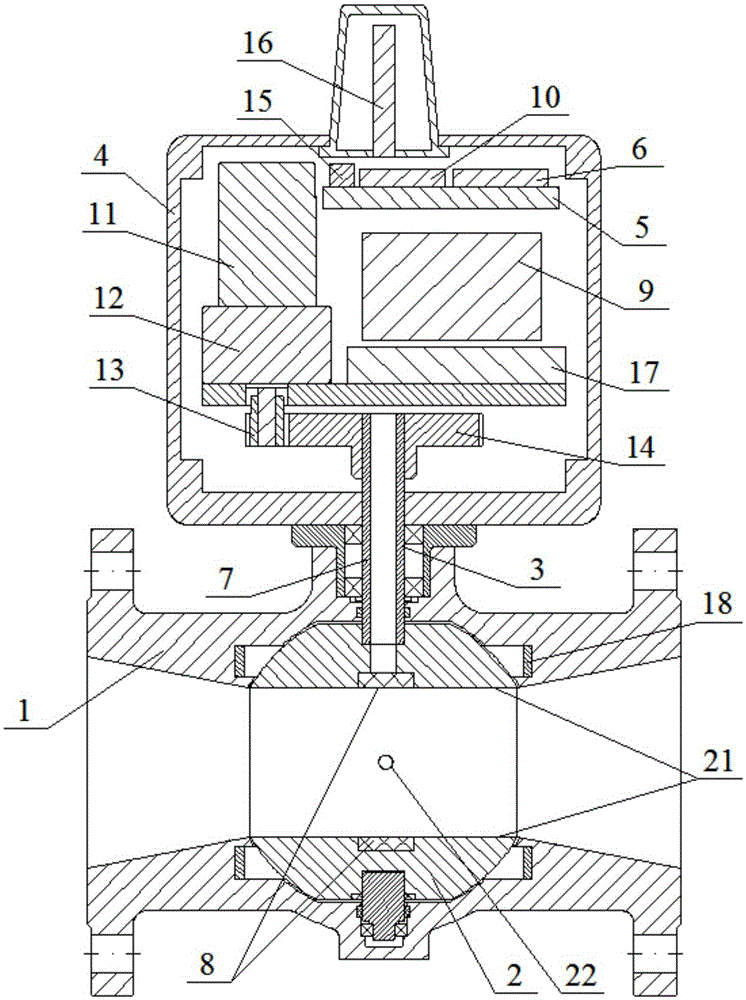
[0029] Such as figure 1 The electromagnetic metering ball valve shown includes a valve body 1, a ball core 2 inside the valve body 1, a valve stem 3 that drives the ball core 2 to rotate, and an electric control box 4 outside the valve body 1; Fluid through hole 21 is arranged, and the paired electrode 22 that is arranged with electromagnetic induction coil 8 and is arranged in the magnetic field scope of electromagnetic induction coil 8 oppositely is provided with in fluid through hole 21, and fluid flows through electromagnetic induction coil 8 and electrode 22 and An induced current is generated on the electrode 22; a circuit board 5 is arranged in the electric control box 4; the electromagnetic induction coil 8 is electrically connected with the circuit board 5 through a wire to form a closed loop; the electrode 22 is connected with the circuit board 5 through a wire; A processing module 6 for obtaining real-time flow information of the fluid by processing the induced curr...

Embodiment 2

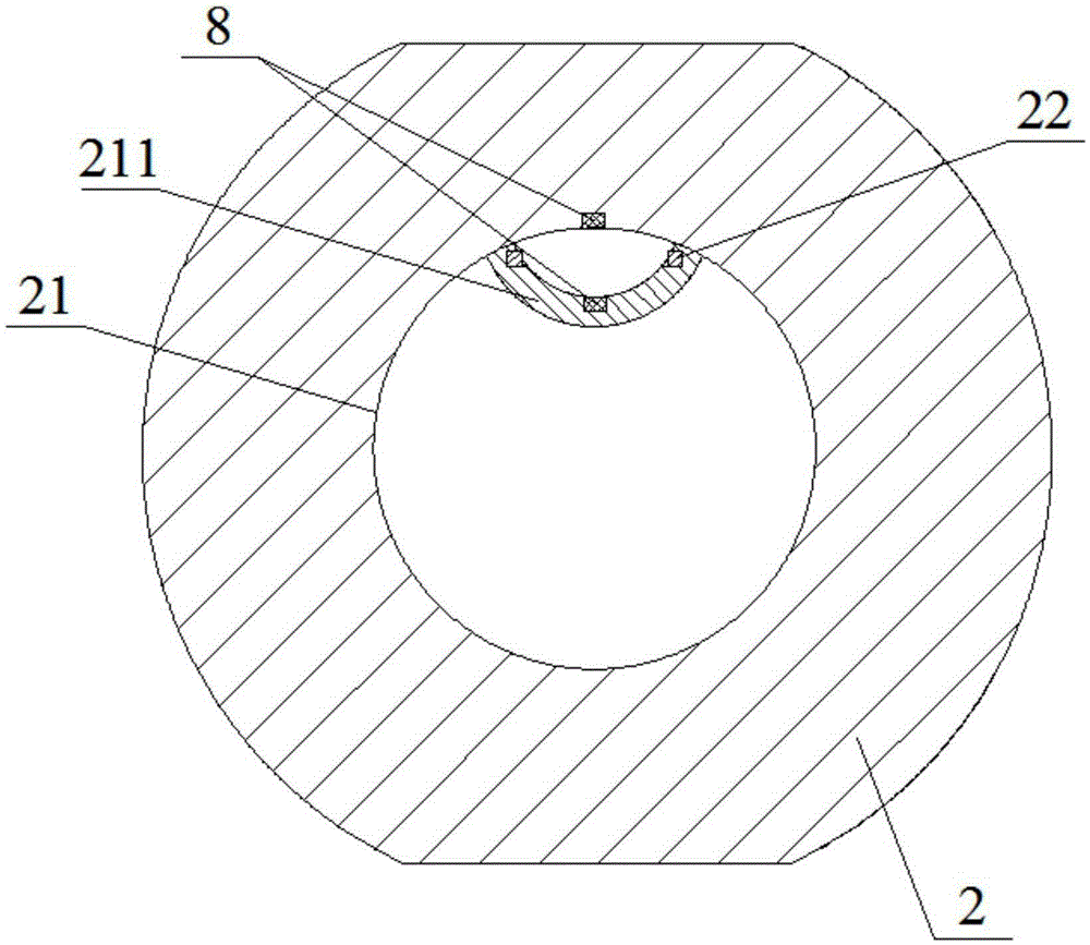
[0035] Such as figure 2 , 3 As shown, the structure of the electromagnetic metering ball valve in the present invention is basically the same as that of Embodiment 1, the difference is that a hollow flow measuring tube 211 is arranged on the inner wall of the fluid through hole 21, and the arrangement direction of the flow measuring tube 211 is the same as that of the fluid through hole 21. The directions are consistent; the electromagnetic induction coil 8 is arranged on the inner wall of the flow tube 211 . The flow tube 211 and the fluid through hole 21 share a part of the side wall, and the flow tube 211 and the fluid through hole 21 are integrally formed. The electromagnetic induction coil 8 is preferably arranged on the side wall shared by the flow tube 211 and the fluid through hole 21 . The electrodes 22 are embedded and arranged on opposite side walls of the fluid through hole 21 and / or the flow tube 211 perpendicular to the fluid direction.

[0036] The principle...


PUM


Abstract

The invention discloses an electromagnetic metering ball valve which comprises a valve body, a ball core, a valve rod and an electronic control box, wherein fluid through holes are formed in the ball core; paired electrodes are arranged in the fluid through holes, are provided with electro-magnetic induction coils in a relative manner, and are arranged in the magnetic field range of the electro-magnetic induction coils; fluid flows through the electro-magnetic induction coils and the electrodes and generates induced current in the electrodes; a circuit board is arranged in the electronic control box; a processing module capable of processing the induced current of the electrodes to obtain the real-time flow information of fluid is arranged on the circuit board. The electromagnetic metering ball valve has the following benefits: the electromagnetic metering manner is adopted to measure fluid flow, so that the measuring accuracy is high, the problem that a valve and a flowmeter are mounted separately in a pipeline is solved, and the cost is reduced; opening and closing of a butterfly bamper can be realized in a remote wireless control manner according to real-time flow, and the remote wireless control manner according to real-time flow is suitable for unified automated management, and remote control and maintenance of the pipeline.

Description

technical field [0001] The invention relates to the technical field of valves and fluid metering, in particular to an electromagnetic metering ball valve. Background technique [0002] The ball valve is not only simple in structure and good in sealing performance, but also has the advantages of small size, light weight, less material consumption, small installation size, small driving torque, easy operation, and easy quick opening and closing within a certain nominal size range. One of the fastest growing valve varieties in the past ten years. [0003] The use of ball valves is very extensive, and the variety and quantity of use are still expanding, and they are developing in the direction of high temperature, high pressure, large diameter, high sealing, long life, excellent adjustment performance, and one valve with multiple functions. Its functional diversity has become an important indicator to show the technical level of the national valve industry, and it is also an im...

Claims


Application Information

Patent Timeline
IPC IPC(8): F16K31/04F16K37/00
CPCF16K31/046F16K37/0091
Inventor 黄忠李进武陆勇喜
Owner 武汉卓瑞芯科技有限公司
Why Eureka
Try Eureka