Cooling tower used for iron and steel industry

A technology for iron and steel industry and cooling towers, applied in water shower coolers, direct contact heat exchangers, heat exchanger types, etc., which can solve problems such as restricting the development of enterprises

Inactive Publication Date: 2016-01-13
XINXIELI PRESS PLATE
View PDF14 Cites 2 Cited by
  • Summary
  • Abstract
  • Description
  • Claims
  • Application Information

AI Technical Summary

Problems solved by technology

[0004] There are big problems in the use of the above two kinds of cooling, which restrict the development of enterprises to a certain extent

Method used


Image

  • Cooling tower used for iron and steel industry

Examples


Embodiment Construction

[0013] The preferred embodiments of the present invention are described in detail below, so that the advantages and features of the present invention can be more easily understood by those skilled in the art, so as to define the protection scope of the present invention more clearly.

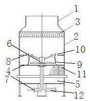
[0014] Described in the present invention is a kind of cooling tower for iron and steel industry, see figure 1 As shown, it includes a wind guide tube 1, a tower body 2, a water eliminator 3, a plane screen 4, a water collection tray 5, a spray propulsion device 6 and a water inlet pipe 7.

[0015] The air guide tube 1 is arranged on the top of the tower body 2 in an open structure.

[0016] The water eliminator 3 is arranged laterally on the upper part of the tower body 2 .

[0017] The plane screen 4 is arranged in the middle of the tower body 2 .

[0018] Further, a side screen 8 is arranged on the tower body 2 above the plane screen 4 .

[0019] Further, a spacer 9 is also arranged on the...


PUM


Abstract

The invention discloses a cooling tower used for the iron and steel industry. The cooling tower comprises an air guide cylinder, a tower body, a water collector, a planar screen, a water collecting disc, a spray pushing device and a water inlet pipe. The air guide cylinder is of an open structure and is arranged at the top end of the tower body. The water collector is arranged on the upper portion of the tower body transversely. The planar screen is arranged in the middle of the tower body. The water collecting disc is arranged on the lower portion of the tower body. The spray pushing device is arranged above the center of the planar screen. One end of the water inlet pipe is arranged below the spray pushing device, and the other end of the water inlet pipe is arranged at the bottom of the tower body. A water outlet pipe is further arranged below the water collecting disc. The cooling tower used for the iron and steel industry is simple in structure, no motor or speed reducer or electric-control equipment or filler is used, the cooling effect is stable, the operation weight is low, energy is saved, and operation and maintenance management is convenient.

Description

technical field [0001] The invention relates to the field of mechanical equipment, in particular to a cooling tower for the iron and steel industry. Background technique [0002] The iron and steel industry often requires the use of cooling towers. There are many cooling towers in the prior art, such as steel-concrete structure counter-flow mechanical ventilation cooling towers, equipped with 4.7m axial flow fans and 30kW motors. The average annual fan start-up time is 200 days. In practical application, due to the high hardness of the circulating water, the water distribution nozzle and the concrete grid plate are seriously scaled. During the use of the cooling tower axial flow fan, due to the large diameter of the fan and the mass of the blade, its moment of inertia is also large; at the same time, due to the difference in the quality of the blade and the difficulty in controlling the installation accuracy, the vibration is relatively large, which is likely to shorten the ...

Claims


Application Information

Patent Timeline
IPC IPC(8): F28C1/00F28F25/12F28F25/02
Inventor 梅亚波
Owner XINXIELI PRESS PLATE
Why Eureka
Try Eureka