Auxiliary LDO circuit and switching supply circuit

A power supply circuit and circuit technology, which is applied in the direction of adjusting electrical variables, control/regulation systems, instruments, etc., can solve the problems of large power consumption and system power consumption, and achieve the effects of low power consumption, power saving, and small static current

Inactive Publication Date: 2016-01-13
上海芯圣电子股份有限公司
View PDF6 Cites 15 Cited by
  • Summary
  • Abstract
  • Description
  • Claims
  • Application Information

AI Technical Summary

Problems solved by technology

[0002] In the design of MCU (microprocessor) and other circuits, a sleep (sleep) state with lower power consumption is required, but the digital circuit in the chip system works at a lower power supply voltage, and the power supply of the whole system is high voltage. Therefore, LDO (Low Dropout Regulator) is needed in the system to convert the high-voltage power supply into a low-voltage power supply to supply power to the digital system, but the general LDO requires higher precision and load performance, so the power consumption of the LDO will be higher. It is relatively large, and it is also necessary to turn on the LDO in the sleep state. Only when the LDO is turned on can the system be in a state of waking up at any time, which makes the overall power consumption of the system in the sleep state will be relatively large.

Method used


Image

  • Auxiliary LDO circuit and switching supply circuit
  • Auxiliary LDO circuit and switching supply circuit
  • Auxiliary LDO circuit and switching supply circuit

Examples


Embodiment 1

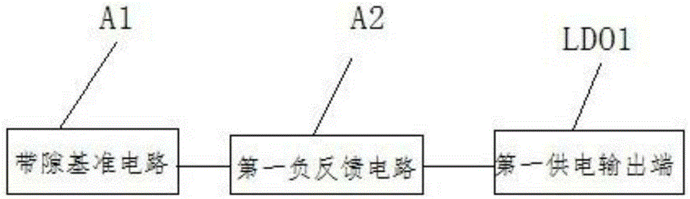
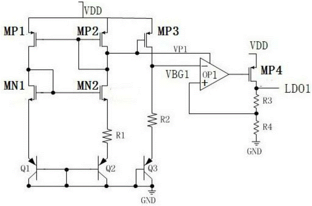
[0028] Such as figure 1 and figure 2 As shown, the auxiliary LDO circuit in this embodiment includes: a bandgap reference circuit A1 for generating a reference voltage; a first negative feedback circuit A2 for supplying power to a load, and the first negative feedback circuit A2 and the bandgap The gap reference circuit A1 is connected; the first power supply output terminal is connected with the first negative feedback circuit. After the power supply is powered on, the bandgap reference circuit A1 will generate a reference voltage of about 1.2V and provide it to the first negative feedback circuit A2, which will generate power supply through the first negative feedback circuit A2, and output it to the external load through the first power supply output terminal LDO1 or other circuits.

[0029] The bandgap reference circuit A1 includes a first PMOS transistor MP1, a second PMOS transistor MP2, a third PMOS transistor MP3, a first NMOS transistor MN1, a second NMOS transisto...

Embodiment 2

[0040] In this embodiment, the auxiliary LDO circuit is applied to the switching power supply circuit, such as Figure 4 , Figure 5 , Figure 6 and Figure 7 shown.

[0041] This embodiment provides a switching power supply circuit, including: an auxiliary LDO circuit; a main LDO circuit, the main LDO circuit includes a second negative feedback circuit A3, a VBG module that provides a reference voltage to the second negative feedback circuit A3, and the second The third switch S3 connected to the negative feedback circuit A3; the CTRL circuit connected to the second negative feedback circuit in the auxiliary LDO circuit and the main LDO circuit respectively. The auxiliary LDO circuit is referred to as "auxiliary LDO" in the drawings, the main LDO circuit is referred to as "main LDO", and the CTRL circuit is referred to as "CTRL".

[0042] The second negative feedback circuit A3 includes a second operational amplifier OP2, a fifth PMOS transistor MP5, a fifth resistor R5 a...


PUM


Abstract

The invention discloses an auxiliary LDO circuit and a switching circuit. The auxiliary LDO circuit comprises a band-gap reference circuit used for generating reference voltage, and a first negative feedback circuit used for powering a load. The first negative feedback circuit is connected with the band-gap reference circuit. The auxiliary LDO circuit further comprises a first power supply output end used for powering a load. The first power supply output end is connected with the first negative feedback circuit.In a chip system, the band-gap reference circuit offers reference voltage to the first negative feedback circuit when a digital circuit is in the sleep state. The load is supplied with power via the first power supply output end. Due to the fact that all devices of the auxiliary LDO circuit work in a sub-threshold region, an MOS tube consumes low quiescent current in the sub-threshold region in the band-gap reference circuit such that little power consumption is generated by the overall circuit, thereby saving electric energy.

Description

technical field [0001] The invention relates to an integrated circuit, in particular to an auxiliary LDO circuit and a switching power supply circuit used in a sleep state. Background technique [0002] In the design of MCU (microprocessor) and other circuits, a sleep (sleep) state with lower power consumption is required, but the digital circuit in the chip system works at a lower power supply voltage, and the power supply of the whole system is high voltage. Therefore, LDO (Low Dropout Regulator) is needed in the system to convert the high-voltage power supply into a low-voltage power supply to supply power to the digital system, but the general LDO requires higher precision and load performance, so the power consumption of the LDO will be higher. It is relatively large, and it is also necessary to turn on the LDO in the sleep state. Only when the LDO is turned on can the system be in a state of waking up at any time, which makes the overall power consumption of the system...

Claims


Application Information

Patent Timeline
Patent Type & Authority Applications(China)
IPC IPC(8): G05F1/56
Inventor 刘启付王铭义袁奥马洋
Owner 上海芯圣电子股份有限公司
Why Eureka
Try Eureka