
Method for detecting position of surface-mounted permanent magnet synchronous motor rotor

A technology of permanent magnet synchronous motor and rotor position, which is applied in the direction of control of generator, motor generator control, control of electromechanical transmission, etc., can solve problems such as influence, and achieve the effect of eliminating delay problem and accurate rotor position estimation

Active Publication Date: 2016-01-13
NANJING UNIV OF AERONAUTICS & ASTRONAUTICS
View PDF4 Cites 12 Cited by
  • Summary
  • Abstract
  • Description
  • Claims
  • Application Information

AI Technical Summary

Problems solved by technology

[0003] The technical problem to be solved by the present invention is to provide a detection method for the rotor position of a surface-mounted permanent magnet synchronous motor, which eliminates the band-pass and low-pass filters, and eliminates the delay caused by the filter. The time problem makes the rotor position estimation more accurate, and solves the technical problems that the influence of the filter delay on the system cannot be avoided in the prior art and the simple omission of the band-pass filter affects the position estimation accuracy.

Method used


Image

  • Method for detecting position of surface-mounted permanent magnet synchronous motor rotor
  • Method for detecting position of surface-mounted permanent magnet synchronous motor rotor
  • Method for detecting position of surface-mounted permanent magnet synchronous motor rotor

Examples


Embodiment Construction

[0032] In order to more clearly illustrate the technical solutions of the embodiments of the present invention, the following will briefly introduce the accompanying drawings that need to be used in the description of the embodiments. Obviously, the accompanying drawings in the following description are only some embodiments of the present invention. For Those of ordinary skill in the art can also obtain other drawings based on these drawings without any creative effort.

[0033] Embodiments of the present invention will be described in detail below, and the embodiments described below with reference to the accompanying drawings are exemplary, and are only used to explain the present invention, and cannot be construed as limiting the present invention.

[0034] Those skilled in the art can understand that, unless otherwise defined, all terms (including technical terms and scientific terms) used herein have the same meaning as commonly understood by one of ordinary skill i...


PUM


Abstract

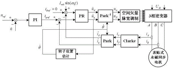
The invention discloses a method for detecting the position of a surface-mounted permanent magnet synchronous motor rotor, belonging to the technical field of motor control. The method comprises the steps of injecting high-frequency current to a d axis of an estimated rotor synchronous coordinate system, and controlling the current under the estimated rotor synchronous coordinate system to be consistent with a given value; when the current under the estimated rotor synchronous coordinate system is controlled to be consistent with the given value, extracting a 1kHz component in the q-axis voltage of the estimated rotor synchronous coordinate system, modulating the extracted 1kHz component and a same-phase high-frequency signal to eliminate 2kHz harmonic, and extracting a direct-current component to obtain an estimated position error signal, thus saving band-pass and low-pass filters, eliminating the delay problem caused by the filters and estimating the position of the rotor more accurately.

Description

technical field [0001] The invention discloses a detection method for the rotor position of a surface-mounted permanent magnet synchronous motor, which belongs to the technical field of motor control. Background technique [0002] At present, for the low-speed positionless control method of the surface-mounted permanent magnet synchronous motor, the common high-frequency signal injection method is the main method. The document "SPMSM low-speed position sensorless control based on pulse-vibration high-frequency current injection" (Liu Ying, Zhou Bo, Zhao Chengliang, Chinese Journal of Electrotechnical Society, 2012, 7(27):139-145.) used the pulse-vibration high-frequency current injection method for the first time To realize the rotor position estimation of SPMSM, traditional band-pass and low-pass filters are used for signal processing. Many articles that study high-frequency signal injection methods also use band-pass and low-pass filters for high-frequency signal processi...

Claims


Application Information

Patent Timeline
IPC IPC(8): H02P21/18
Inventor 倪天恒周波刘兵王龙
Owner NANJING UNIV OF AERONAUTICS & ASTRONAUTICS
Learn More