
Axial rotary module for minimally invasive instruments

An axial and instrumental technology, which is applied in the field of joint modules of minimally invasive surgical instruments, can solve problems such as delicate structure, flexible transmission, unreasonable design of instrument joint modules, and less degrees of freedom, and achieve good versatility. , enrich the structure types, reduce the effect of structure size

Active Publication Date: 2017-09-29
TIANJIN UNIV
View PDF7 Cites 0 Cited by
  • Summary
  • Abstract
  • Description
  • Claims
  • Application Information

AI Technical Summary

Problems solved by technology

The terminal instrument of the Zeus minimally invasive surgical robot system is a two-degree-of-freedom instrument driven by a connecting rod, which has the problems of few degrees of freedom and complex structure; the terminal instrument of the Da Vinci system has good flexibility, but its structure is complicated; internationally, such as The United States, Germany, Japan, Poland and other scientific research institutions have successively developed terminal instruments for minimally invasive surgical robots, but most of them have shortcomings such as complex structure, low flexibility, and poor operability. One of the reasons for the above situation is the joint module of the instrument. The design is unreasonable, and it is difficult to meet the requirements of exquisite structure and flexible transmission

Method used


Image

  • Axial rotary module for minimally invasive instruments
  • Axial rotary module for minimally invasive instruments
  • Axial rotary module for minimally invasive instruments

Examples


Embodiment Construction

[0030] The present invention will be described in detail below in conjunction with specific embodiments.

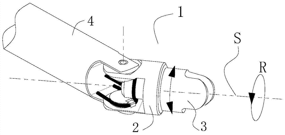
[0031] As shown in the figure, the axial rotation module 1 of the minimally invasive instrument includes a support base 2 and a rotation base 3 . The revolving base 3 passes through the support base 2 and is connected to the support base 2 in rotation. The support base 2 is coaxial with the revolving base 3 and is the axis of rotation of the revolving module 1. In the revolving base 3 The rear end provided through the support base 2 is connected with a rotary drive device, and the rotary seat 3 can rotate around the central axis of the rotary seat 3 under the drive of the rotary drive device.

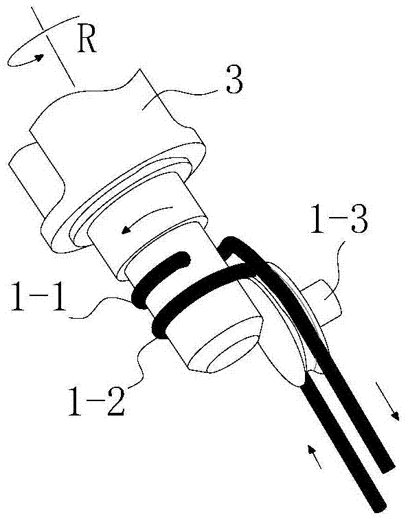
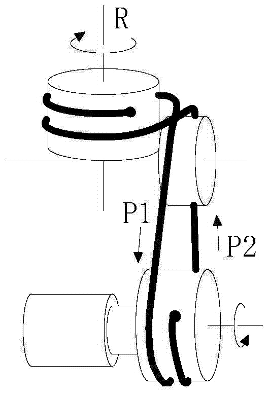
[0032] As the first structure of the slewing drive device of the present invention: the rear end shaft diameter of the slewing base 3 is respectively fixed with two strands of steel wire ropes I1-1 and II1-2 that are revolving forwardly and reversely, and the two strands of steel w...


PUM


Abstract

The invention discloses an axial revolution module of a minimally invasive apparatus. The axial revolution module comprises a support pedestal and a revolution seat; the revolution seat passes through the support pedestal and is connected with the support pedestal in a rotating mode; the support pedestal and the revolution seat share an axis being a revolution axis of the revolution module. A revolution drive unit is connected to the rear end, passing through the support pedestal, of the revolution seat. The revolution seat can rotate around the central axis of the revolution seat under the drive of the revolution drive unit. The revolution drive unit contains a positive rotation steel wire rope I and a reversed rotation steel wire rope II, wherein the positive rotation steel wire rope I and the reversed rotation steel wire rope II are fixed at the rear end axle diameter of the revolution seat; the steel wire rope I and the steel wire rope II with opposite rotation directions are guided by guiding wheels respectively and then are wound at a wire fixing mechanism in a tensioning mode; the wire fixing mechanism is connected with a rotation drive unit; and the guiding wheels are installed on the support pedestal by a guiding wheel shaft in a rotating mode. According to the invention, the structure is simple; and a few parts are used. The axial revolution module is connected with the rear drive nit in a wire transmission mode, thereby simplifying the complexity of the apparatus and reducing the structural dimension.

Description

technical field [0001] The invention relates to a joint module of a surgical instrument, in particular to a joint module of a minimally invasive surgical instrument. Background technique [0002] Minimally invasive surgery represented by laparoscopy is known as one of the important contributions of medical science to human civilization in the 20th century, and is the main theme of global surgical development in the 21st century. In minimally invasive surgery, doctors use modern medical imaging equipment such as thoracic and laparoscopes to perform surgical operations by manipulating the matching minimally invasive surgical instruments. The advantages of fast recovery time greatly reduce the pain suffered by patients, and are widely used in clinical operations. However, it should be pointed out that under the constraints of minimally invasive technology, complex surgical operations become very difficult, which requires more stringent surgical skills for doctors, and also put...

Claims


Application Information

Patent Timeline
Patent Type & Authority Patents(China)
IPC IPC(8): A61B90/00A61B17/00
Inventor 王树新杨英侃孔康李建民李进华
Owner TIANJIN UNIV
Learn More