
Material transferring device

A technology for handling devices and materials, applied in the field of robots, can solve problems such as injury to workers, increase work intensity, and large limitations, and achieve the effects of low production costs, improved work efficiency, and stable operation.

Active Publication Date: 2016-01-20
青岛沃德芯软件有限公司
View PDF5 Cites 4 Cited by
  • Summary
  • Abstract
  • Description
  • Claims
  • Application Information

AI Technical Summary

Problems solved by technology

[0002] In the high-speed automatic production process of materials, especially tubular objects or columns, after the front-end processing is completed, the further processed materials need to be transported to the subsequent processing device. The traditional material handling is carried out manually, and there is no set for it. Although the automation equipment for this operation can also be operated, it increases the work intensity of people, has low efficiency, high cost, and has great limitations.
When the material to be transported is a high-risk material such as high temperature or radioactivity, manual handling requires wearing protective equipment and may cause injury to the staff

Method used


Image

  • Material transferring device
  • Material transferring device

Examples


Embodiment Construction

[0023] In order to make the purpose and features of the present invention more obvious and easy to understand, the following will further describe the specific embodiments of the present invention in conjunction with the accompanying drawings. However, the present invention can be realized in different forms, and should not be considered as being limited to the described embodiments .

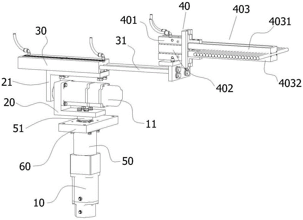
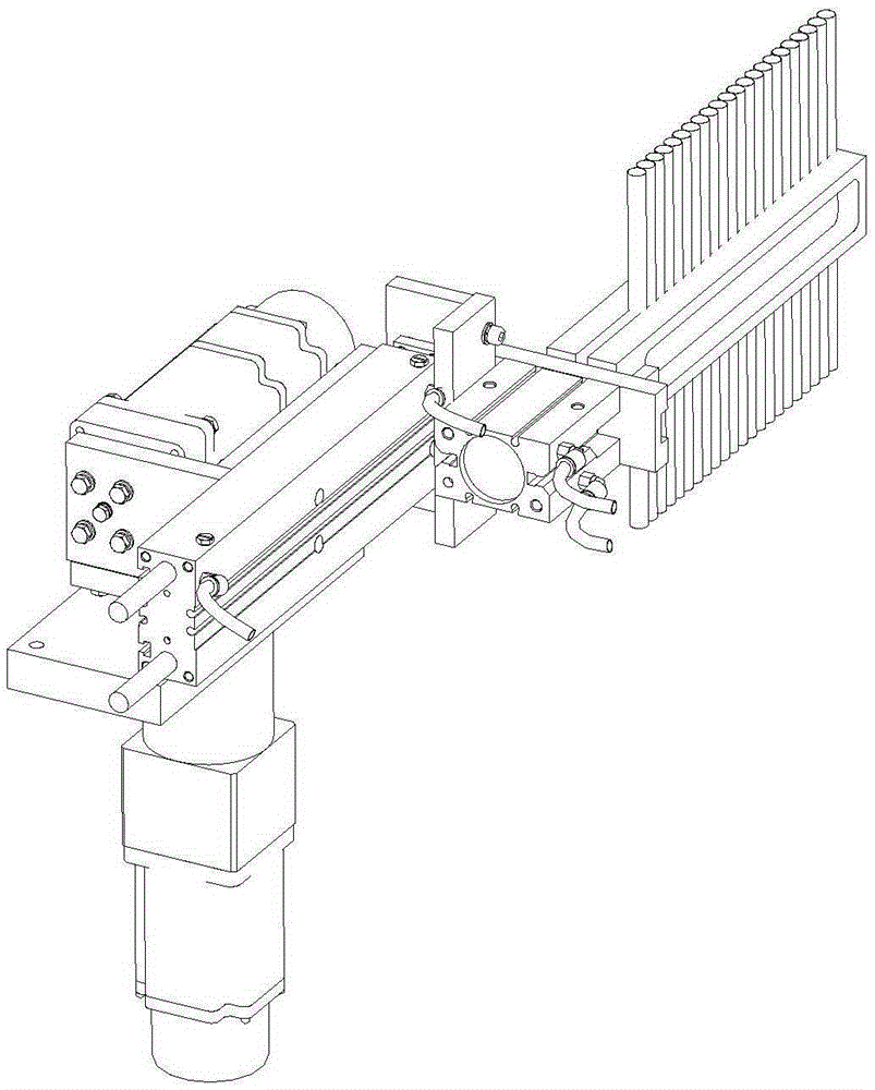
[0024] Such as figure 1 and figure 2 Shown is a perspective view of a preferred embodiment of the material handling device of the present invention. In this embodiment, the first drive unit is the servo motor a10, and the second drive unit is the servo motor b11. In the figure, the rotating shaft flange 51 is movably installed on the support plate 60 through bearings, and is connected with the reducer 50 through a key to realize synchronous rotational movement. The speed reducer 50 is fixedly connected to the support plate 60 by bolts, and the support plate 60 is fixed on the external frame...


PUM


Abstract

The invention provides a material transferring device which comprises a driving part, a transferring part and a clamping part. The driving part comprises a first driving unit and a second driving unit. The transferring part comprises a reversing unit and a stretching-and-retracting unit. The reversing unit comprises a first reversing unit body and a second reversing unit body. The first driving unit is movably connected with the first reversing unit body. The first driving unit drives the first reversing unit body to conduct first rotation movement. The second driving unit is fixedly connected with the first reversing unit body, the second driving unit is movably connected with the second reversing unit body, the second driving unit drives the second reversing unit to conduct second rotation movement. The stretching-and-retracting unit is fixedly connected with the second reversing unit body. The tail end of the stretching-and-retracting unit is connected with the clamping part. By means of the material transferring device, manual work can be well replaced, materials are transferred stably and reliably, the working efficiency is improved, and production cost is reduced.

Description

technical field [0001] The invention relates to the technical field of robots, in particular to a material handling device. Background technique [0002] In the high-speed automatic production process of materials, especially tubular objects or columns, after the front-end processing is completed, the further processed materials need to be transported to the subsequent processing device. The traditional material handling is carried out manually, and there is no set for it. Although the automation equipment for this operation can also be operated, it increases the work intensity of people, has low efficiency, high cost, and large limitations. When the material to be transported is a high-risk material such as high temperature or radioactivity, manual handling requires wearing protective equipment and may cause injury to the staff. Therefore, there is a need for a stable and reliable material handling device to replace labor, improve work efficiency, and reduce production cos...

Claims


Application Information

Patent Timeline
Patent Type & Authority Applications(China)
IPC IPC(8): B65G47/90
Inventor 李泽伟
Owner 青岛沃德芯软件有限公司
Learn More