
Automotive LED headlamp

A technology of LED chips and headlights, applied in the direction of headlights, vehicle parts, cooling/heating devices of lighting devices, etc. The effect of output light intensity and improving light efficiency

Inactive Publication Date: 2016-01-20
XIAN RUILAITE AUTOMOTIVE TECH CO LTD
View PDF6 Cites 5 Cited by
  • Summary
  • Abstract
  • Description
  • Claims
  • Application Information

AI Technical Summary

Problems solved by technology

[0003] As a huge system in the automotive industry, its lighting system will also develop with the advancement of science and technology. At present, foreign auto giants have invested huge sums of money in the development of LED headlights, and they have been put on the market in small quantities in some high-end models, but LED headlights for automobiles are facing some technical difficulties. It is difficult to increase the power of a single chip, and the combination of multiple chips faces the problem of light convergence. The projected light type of car lights is the most important parameter of car lights, which directly affects driving safety. In terms of light convergence, the methods currently used are mostly reflective and special-shaped resin lenses, both of which are not ideal in terms of light convergence. One thorny issue is the heat dissipation of LEDs
[0004] Thermal resistance is the ability to prevent the heat emitted by the LED chip from being quickly transferred to the heat dissipation system. Of course, the lower the better, the thermal resistance is also a direct factor affecting the light efficiency and power of the LED. It is possible to solve the thermal resistance of the chip well. Taking advantage of the high light efficiency of LEDs, it is impossible to use a large radiator in a car due to its mobility and limited space. Even if the heat dissipation is conditional and there is no low thermal resistance, it will cause the LED chip to overheat, shorten its life and even burn it. To solve the heat dissipation of LED well

Method used


Image

  • Automotive LED headlamp
  • Automotive LED headlamp
  • Automotive LED headlamp

Examples


Embodiment Construction

[0018] The present invention will be further described in detail below in conjunction with specific embodiments, which are explanations of the present invention rather than limitations.

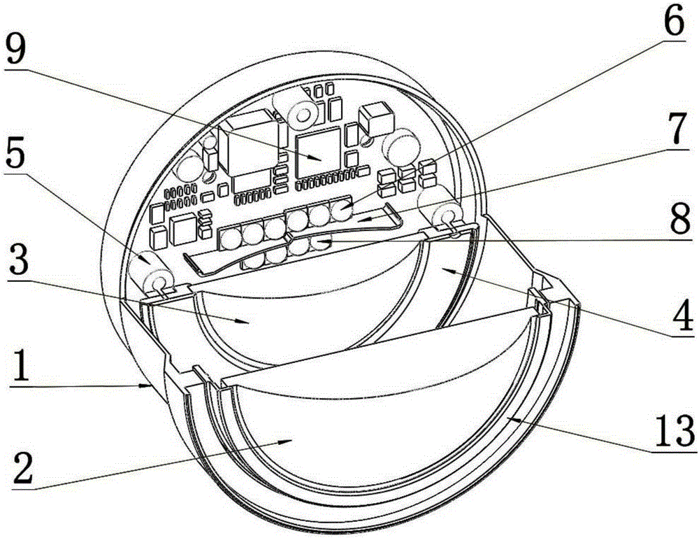
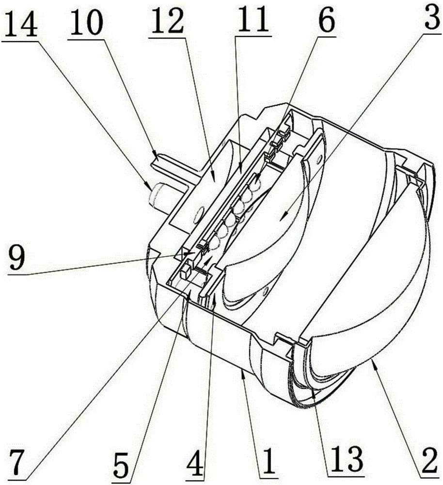
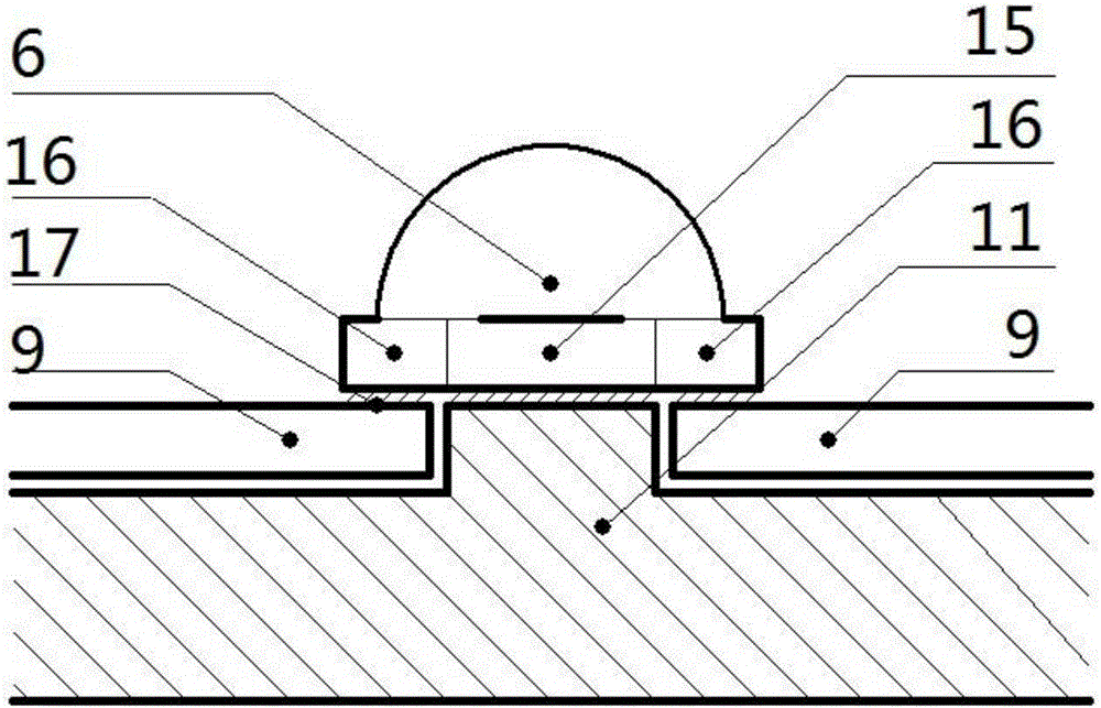
[0019] see Figure 1 to Figure 3 , a kind of LED vehicle headlamp, comprises lamp housing 1, first lens 2 and second lens 3; Lamp housing 1 is provided with focusing ring 13, and focusing ring 13 is fixed with first lens 2, the second The second lens 3 is fixed on the bracket 4, the bracket 4 is installed on the bottom of the lamp housing 1 through the pillar 5, the circuit board 9 is fixed on the bottom of the lamp housing 1, and the low beam LED chip 6 is welded on the front of the circuit board 9 and the high beam LED chip 8, the low beam LED chip 6 and the high beam LED chip 8 are horizontally provided with a light shielding plate 7, the low beam LED chip 6 is located above the light shielding plate 7, and the high beam LED chip 8 is located below the light shielding plate 7, so The fron...


PUM


Abstract

The invention discloses an automotive LED headlamp which comprises a lamp shell, a first lens and a second lens. A focusing ring is arranged on the lamp shell and fixedly provided with the first lens. The second lens is fixed to a support, and the support is arranged at the bottom of the lamp shell through supporting columns. A circuit board is fixed to the bottom of the lamp shell, a light shielding board and two sets of LED unit bodies are welded to the front face of the circuit board, and a heat conduction red copper block is welded to the back face of the circuit board. A sealing cavity is formed between the red copper block and the tail of the lamp shell and connected with a cooling device, and the light shielding board is located between the two LED unit bodies. A double lens assembly is formed by the first lens and the second lens for direct irradiation and light beam convergence, the horizontally-arranged light shielding board is matched for imaging, so that light convergence is good, good light refraction lines are obtained, and light efficiency is further improved; and meanwhile distance light and passing light are combined. Due to the red copper block heat conduction structure, heat resistance of LED chips is lowered, and the light efficiency is improved.

Description

technical field [0001] The invention relates to an LED lamp, in particular to an LED vehicle headlight. Background technique [0002] In recent years, LED lighting, as a new type of green light source, is developing rapidly. Its advantages such as energy saving, high light efficiency and green environmental protection will gradually replace traditional light sources. It has been well verified in household lighting and public road lighting. . [0003] As a huge system in the automotive industry, its lighting system will also develop with the advancement of science and technology. At present, foreign auto giants have invested huge sums of money in the development of LED headlights, and they have been put on the market in small quantities in some high-end models, but LED headlights for automobiles are facing some technical difficulties. It is difficult to increase the power of a single chip, and the combination of multiple chips faces the problem of light convergence. The proj...

Claims


Application Information

Patent Timeline
IPC IPC(8): F21S8/10F21V5/04F21V14/06F21V17/10F21V19/00F21V29/50F21V11/00F21V29/56F21W101/10F21Y115/10
CPCF21S41/40F21S41/635F21S43/14F21S45/46F21S45/49F21W2102/00F21S41/143F21S41/151F21S41/192F21S41/255F21S41/43F21Y2105/10F21Y2105/12
Inventor 焦栋青
Owner XIAN RUILAITE AUTOMOTIVE TECH CO LTD
Learn More