Downhole optical fiber distributed flow monitoring system

An optical fiber distributed, flow monitoring technology, applied in the direction of measuring flow/mass flow, liquid/fluid solid measurement, measuring devices, etc., can solve the problems of low signal-to-noise ratio of demodulated signals, difficult to measure accurately, and low signal-to-noise ratio , to achieve the effect of reducing environmental noise, large dynamic range, and improving signal-to-noise ratio

Active Publication Date: 2016-01-20
LASER RES INST OF SHANDONG ACAD OF SCI
View PDF5 Cites 17 Cited by
  • Summary
  • Abstract
  • Description
  • Claims
  • Application Information

AI Technical Summary

Problems solved by technology

[0007] (2) Using the scattering principle, the signal-to-noise ratio of the demodulated signal is low, and it is difficult to measure accurately at low flow rates
Its system adopts the principle of optical fiber scattering, resulting in a low signal-to-noise ratio of the system. The scheme in its patent can realize the acoustic wave signal with a relatively large sound pressure directly acting on the optical fiber, and does not have the ability to detect the flow information in the downhole pipe.

Method used


Image

  • Downhole optical fiber distributed flow monitoring system
  • Downhole optical fiber distributed flow monitoring system
  • Downhole optical fiber distributed flow monitoring system

Examples


Embodiment Construction

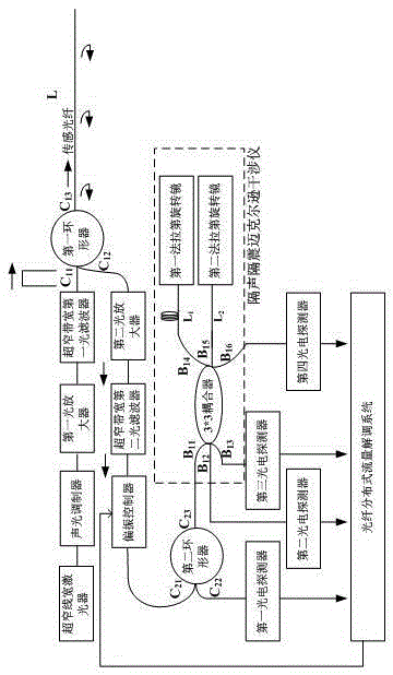
[0063] Such as figure 1 As shown, a downhole optical fiber distributed flow monitoring system includes an ultra-narrow linewidth laser, and the ultra-narrow linewidth laser emitted by the ultra-narrow linewidth laser is modulated by an acousto-optic modulator into a pulse with a pulse width of τ and a period of T Pulsed laser, the pulsed laser sequence sequentially passes through the first optical amplifier and the first ultra-narrow bandwidth optical filter, and then enters the C of the first circulator 11 end, the pulsed laser sequence from the C of the first circulator 11 terminal via C 13 The end is injected into the sensing fiber with length L, and the back Rayleigh scattered light in the sensing fiber returns to C of the first circulator 13 terminal, from the first circulator C 12 The back Rayleigh scattered light output from the end passes through the second optical amplifier and enters the ultra-narrow linewidth second optical filter, and the back Rayleigh scattere...


PUM


Abstract

The invention relates to a downhole optical fiber distributed flow monitoring system. The downhole optical fiber distributed flow monitoring system comprises an ultra-narrow line width laser, wherein laser light passes through an acousto-optic modulator, a first light amplifier and an ultra-narrow bandwidth first light filter, then enters a first circulator and then is filled into sensing optical fibers, and Rayleigh back-scattering light in the sensing optical fibers returns back to the first circulator, passes through a second light amplifier, enters an ultra-narrow bandwidth second light filter, passes through a polarization controller, enters a second circulator, then enters a 3x3 coupler, is split into a first faraday rotator mirror, a second faraday rotator mirror and a fourth photoelectric detector; the fourth photoelectric detector feeds electric signals into an optical fiber distributed flow demodulation system; the Rayleigh back-scattering light passes through the 3x3 coupler and enters a second photoelectric detector, a third photoelectric detector and the second circulator, and the second circulator outputs light signals to a first photoelectric detector; the first photoelectric detector, the electric signals of the second photoelectric detector and the third photoelectric detector simultaneously arrive at the optical fiber distributed flow demodulation system.

Description

technical field [0001] The invention relates to the field of optical fiber sensors, in particular to the field of non-immersed downhole optical fiber distributed flow monitoring. Background technique [0002] In the field of oil field, flow measurement can provide extremely important parameters for dynamic monitoring of production and well logging, and oil production and transmission characteristics. Downhole has very harsh environments such as high temperature and high pressure. Traditional electronic flowmeters are prone to failure. Some fiber optic turbines and vortex flowmeters are immersion technologies (such as the invention patent of "Distributed Optical Fiber Flow Measurement Device and Method"), which break the original system flow field and have limitations in measurement results. [0003] The test principle of the invention patent of "Distributed Optical Fiber Flow Measurement Device and Method" is as follows: [0004] By using a sensing optical fiber to connect ...

Claims


Application Information

Patent Timeline
Patent Type & Authority Applications(China)
IPC IPC(8): G01F1/66E21B47/135G01F15/00
Inventor 尚盈刘小会王昌王晨赵文安王英英赵庆超李常马龙翟瑞占
Owner LASER RES INST OF SHANDONG ACAD OF SCI
Why Eureka
Try Eureka