Detection method and system of line fault positioning system of power distribution network

A positioning system and fault positioning technology, applied in the direction of fault location, information technology support system, etc., can solve problems such as inability to detect distribution network automation systems

Active Publication Date: 2016-01-20
HAINAN POWER GRID CO LTD ELECTRIC POWER RES INST
View PDF7 Cites 12 Cited by
  • Summary
  • Abstract
  • Description
  • Claims
  • Application Information

AI Technical Summary

Problems solved by technology

The traditional fault indicator detection system can only detect a single fault indicator, but cannot detect the distribution network automation system.

Method used


Image

  • Detection method and system of line fault positioning system of power distribution network
  • Detection method and system of line fault positioning system of power distribution network
  • Detection method and system of line fault positioning system of power distribution network

Examples


Embodiment 1

[0069] This embodiment describes the specific processing process when the detection system of the distribution network line fault location system of the present invention simulates a simple short-circuit fault.

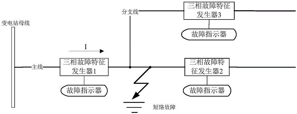
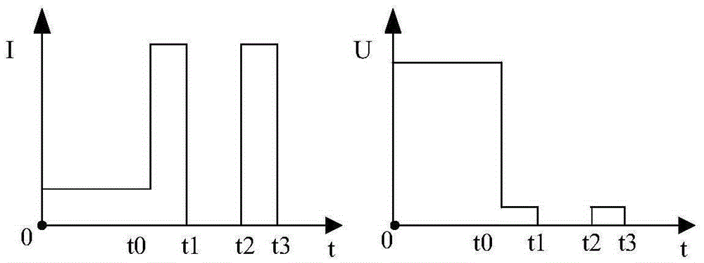
[0070] First of all, the distribution network modeling module of the detection system of the present invention is as follows: figure 2 The line structure shown is modeled, and the three-phase short-circuit fault is set at the fault point and the reclosing is unsuccessful. In this distribution network model, the simulated fault signal of the three-phase fault signature generator 1 is as follows: image 3 set as shown, image 3 Including the setting of timing current and timing voltage. At time T0 when the fault occurs, the current of the line rises sharply and the voltage drops sharply; at time T1, the fault is removed by the relay protection device and circuit breaker of the substation, the current of the line drops to 0A, and the voltage drops to 0V; at time T2, ...

Embodiment 2

[0073] This embodiment describes the specific processing process when the detection system of the distribution network line fault location system of the present invention simulates a single-phase ground fault in the distribution network.

[0074] First of all, the distribution network modeling module of the detection system of the present invention is as follows: Figure 4 The line structure shown is modeled, and phase A is set to ground at the fault point. When A-phase grounding occurs, the A-phase system capacitance in the established distribution network model is short-circuited, so the A-phase system-to-ground capacitance current of each component is 0. The B-phase and C-phase-to-ground system capacitance current of each component must pass through the ground and the fault point to form a loop. The zero-sequence current flow direction in the distribution network model is as follows: Figure 4 I0 is shown.

[0075] In this distribution network model, the characteristics ...


PUM


Abstract

The invention discloses a detection system of a line fault positioning system of a power distribution network. The detection system comprises a main control platform, a communication network and at least one three-phase fault characteristic generator. The main control platform communicates with the three-phase fault characteristic generators via the communication network, and comprises a power distribution network modeling module, a communication management module and a test module. According to the invention, complex power distribution network line faults can be simulated; a complex power distribution network can be established in a modularized, flexible and safe manner; and multiple types of faults can be simulated. Thus, composite test effects of a fault indicator and a fault positioning system can be achieved and all-around detection of fault positioning functions of a power distribution network automatic system can be achieved.

Description

technical field [0001] The invention relates to the technical field of power equipment detection, in particular to a detection method and system for a distribution network line fault location system. Background technique [0002] my country's 10-35kV distribution network widely adopts ungrounded or arc-suppression coil grounding methods, and the structure of the distribution network is complex, the operating environment is harsh, and short-circuit faults and single-phase ground faults are prone to occur. The fault indicator can help operation and maintenance personnel quickly find point of failure. With the development of distribution network automation technology, the fault information of the fault indicator is transmitted to the distribution network automation master station, combined with the geographic information system, to complete the fault location function, which can greatly improve the power supply reliability of the distribution network. [0003] The line fault lo...

Claims


Application Information

Patent Timeline
Patent Type & Authority Applications(China)
IPC IPC(8): G01R31/08
CPCY04S10/52
Inventor 蔡渊谢振超伍人剑朱望诚万信书
Owner HAINAN POWER GRID CO LTD ELECTRIC POWER RES INST
Why Eureka
Try Eureka