Optical Kerr effect-based beam radially smoothing method in inertial confinement fusion device

A technology of inertial confinement fusion and light beams, applied in optics, optical components, instruments, etc., can solve problems such as difficult adjustment and complex optical path structure, and achieve the effect of improving uniformity

Active Publication Date: 2016-01-20
SICHUAN UNIV
View PDF3 Cites 12 Cited by
  • Summary
  • Abstract
  • Description
  • Claims
  • Application Information

AI Technical Summary

Problems solved by technology

However, the three-directional SSD smoothing technology has disadvantages such as complex optical path structure and difficult adjustment

Method used


Image

  • Optical Kerr effect-based beam radially smoothing method in inertial confinement fusion device
  • Optical Kerr effect-based beam radially smoothing method in inertial confinement fusion device
  • Optical Kerr effect-based beam radially smoothing method in inertial confinement fusion device

Examples


Embodiment 1

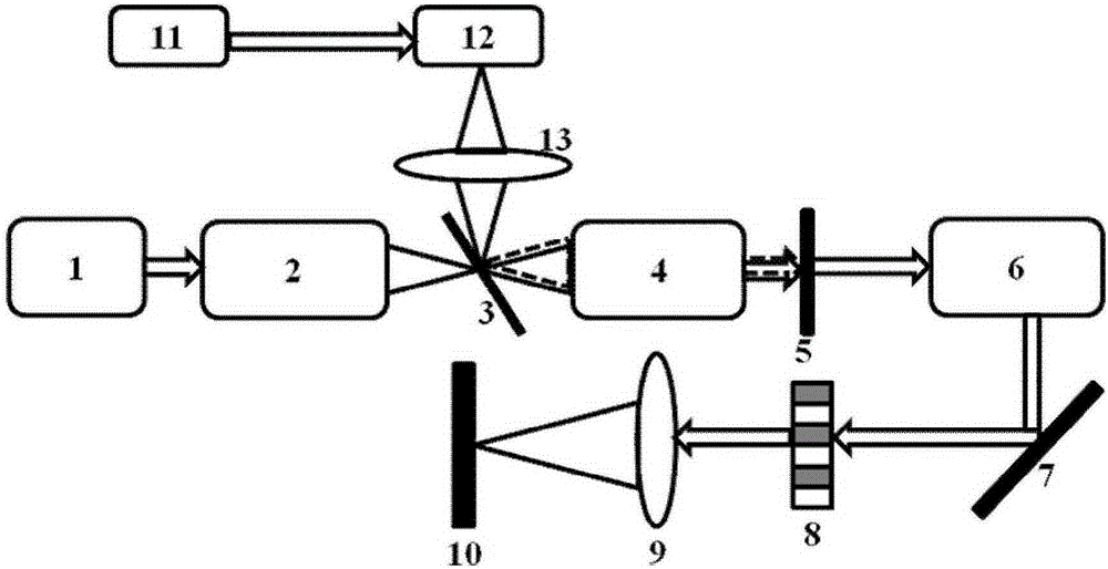
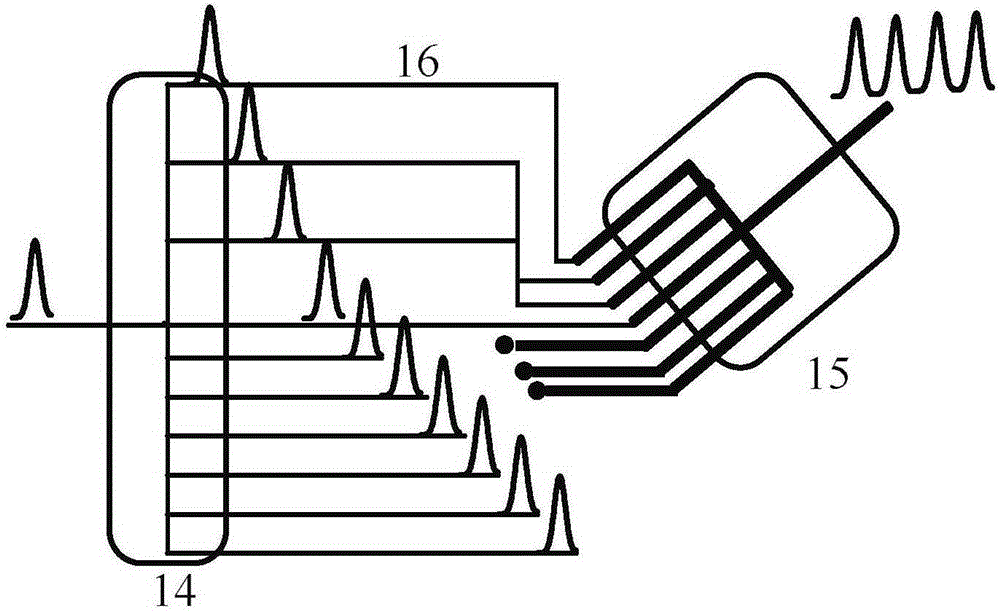
[0053] The optical Kerr medium used in this embodiment is graphene, because of its characteristics such as high optical Kerr coefficient, high damage threshold and large light aperture, the parameters of graphene are: optical Kerr coefficient n 2 =6×10 -8 cm 2 / W, thickness d=0.5nm, size 40×40mm; Gaussian pulse wavelength λ=808nm output by the tunable picosecond laser 11, and the pulse width of full width at half maximum is T w =2.2ps, pulse peak intensity I p =0.2GW / cm 2 , the time delay factor h=3.3 between multiple optical fibers in the fiber pulse stacking unit 12, and the integration time Δt=10ps; the picosecond laser 11 is a tunable picosecond laser; the filter element is an optical rotator.

[0054] The specific operation steps are as follows:

[0055] (1) First, in the optical transmission chain of the laser-driven inertial confinement fusion device, a radial beam smoothing device is added, and the output light wavelength is selected as a tunable picosecond laser 1...

Embodiment 2

[0083] The optical Kerr medium 4 used in this embodiment is carbon disulfide (CS 2 ), its parameter is: optical Kerr coefficient n 2 =2.1×10 -15 cm 2 / W, thickness d=0.45mm, size 40×40mm; the Gaussian pulse wavelength output by the tunable picosecond laser 11 is λ=800nm, and the pulse width T of full width at half maximum w =2.2ps, pulse peak intensity I p =63.5GW / cm 2 , the time delay factor of the fiber pulse accumulation unit 12 is h=3.3, and the integration time Δt=10 ps; the filter element is a filter. The other operation steps and operation process are the same as those in Embodiment 1, and the same effect of improving the uniformity of the far-field focal spot of the laser beam as in Embodiment 1 can also be obtained.


PUM


Abstract

The invention relates to an optical Kerr effect-based beam radially smoothing method and a smoothing device thereof in an inertial confinement fusion device. According to the method, an optical Kerr effect-based beam radially smoothing device is arranged in the optical transmission link of a laser-driven inertial confinement fusion device. Meanwhile, according to the periodic spherical-surface phase modulation under the interactive effect of an optical Kerr medium and periodic Gaussian pulses in the smoothing device, the periodic modulation is conducted before the transmitted wave of a laser beam in the optical transmission link of the inertial confinement fusion device, and the dimension of far-field focal spots thereof is changed in real time. The fast zooming purpose is realized. The fast zooming further causes the radial sweeping of far-field speckles, so that the far-field focal spots of the laser beam are radially smoothed. Finally, the far-field irradiance uniformity of the laser beam is improved within a shorter period of integral time. Namely, the irradiation uniformity of the laser beam on a target surface is improved.

Description

technical field [0001] The invention relates to a beam smoothing technology in a laser-driven inertial confinement fusion device, in particular to a radial beam smoothing method based on the optical Kerr effect in a laser-driven inertial confinement fusion (ICF) device and a smoothing device thereof. Background technique [0002] In laser-driven inertial confinement fusion (ICF) devices, because physical experiments require high-power laser devices to precisely control the light field distribution on the target surface, various spatial and time-domain beam smoothing technologies are widely used. In the ICF device, the control of the uniformity of the far-field focal spot of the laser beam is realized, that is, the uniformity of its irradiation on the target surface is improved. In the existing spatial beam smoothing technology, the continuous phase plate (Continuous Phase Plate, CPP) is often used to control the laser beam far-field focal spot profile, but due to the coheren...

Claims


Application Information

Patent Timeline
Patent Type & Authority Applications(China)
IPC IPC(8): G02B27/09
CPCG02B27/0927G02B27/0955G02B27/0977
Inventor 张彬钟哲强侯鹏程
Owner SICHUAN UNIV
Why Eureka
Try Eureka