

Optical information recording medium, reproduction method, and reproduction device
A technology for recording media and reproducing devices, applied to optical recording/reproducing/erasing methods, optical recording carriers, recording/reproducing with optical methods, etc., to achieve the effect of improving the reproduction quality
- Summary
- Abstract
- Description
- Claims
- Application Information
AI Technical Summary
Problems solved by technology
Method used
Image

Examples
Embodiment approach 1
[0035] Regarding the optical information recording medium according to one embodiment of the present invention, using Figure 1 to Figure 11 for the following description. In addition, in this embodiment, it will be an optical information recording medium (hereinafter referred to as a super-resolution medium) that is a playback-only medium and has a BD (Blu-ray Disc (Blu-ray Disc): registered trademark) type super-resolution region. 1) Described as an example, but not limited thereto. The super-resolution medium 1 may be, for example, an optical information recording medium capable of recording information, or may be a DVD type.
[0036] [Structure of super-resolution medium 1]
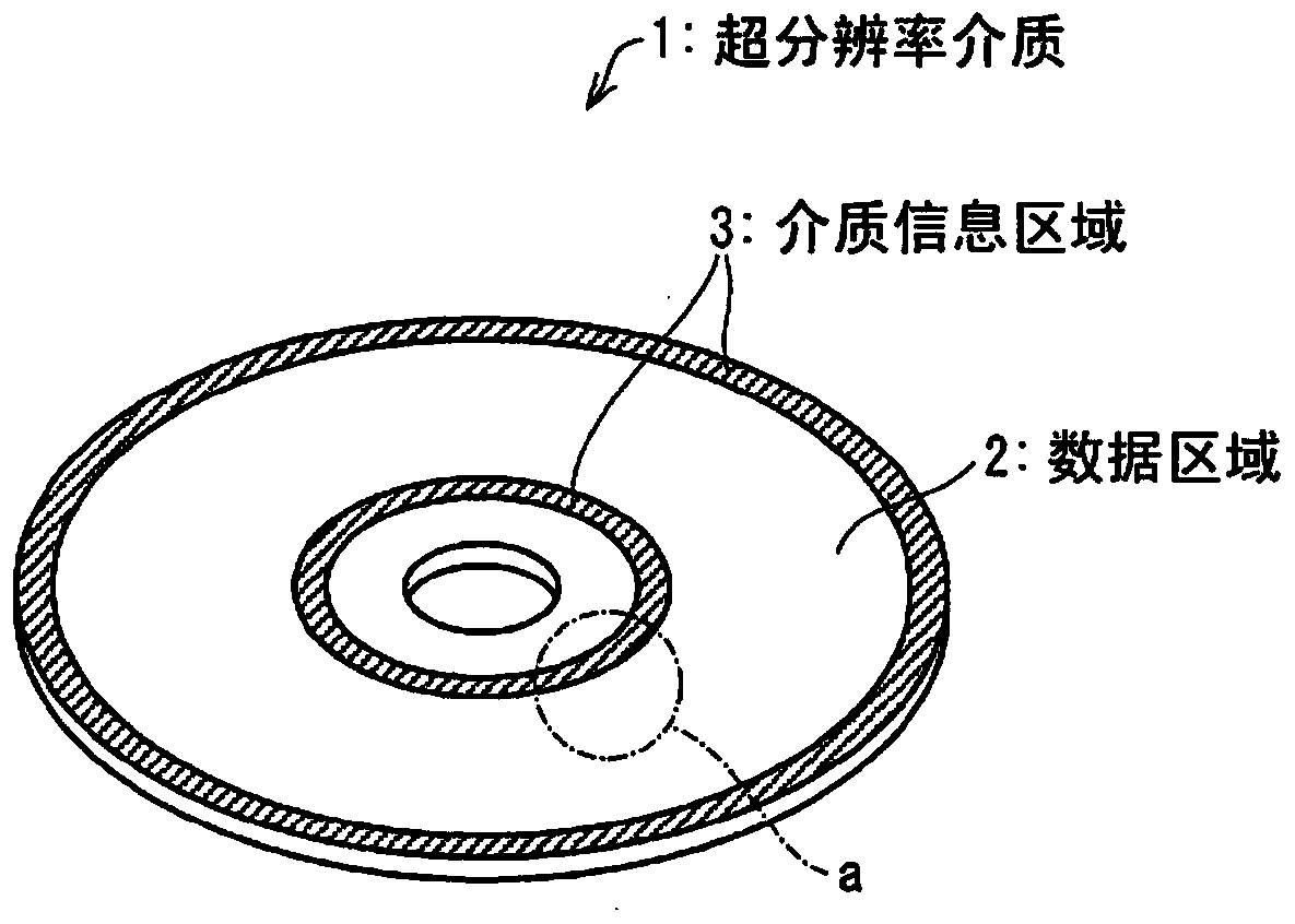
[0037] figure 2 The appearance of the super-resolution medium 1 according to this embodiment is shown. like figure 2 As shown, the super-resolution medium 1 which is a disk-shaped medium has a data area 2 (first area) in which content such as video and software is recorded in advance, and a dat...
Embodiment approach 2
[0135] Regarding another embodiment of the present invention, based on Figure 12 ~ Figure 13 for the following description. In addition, for convenience of description, components having the same functions as those described in the above-mentioned embodiments are denoted by the same reference numerals, and description thereof will be omitted.
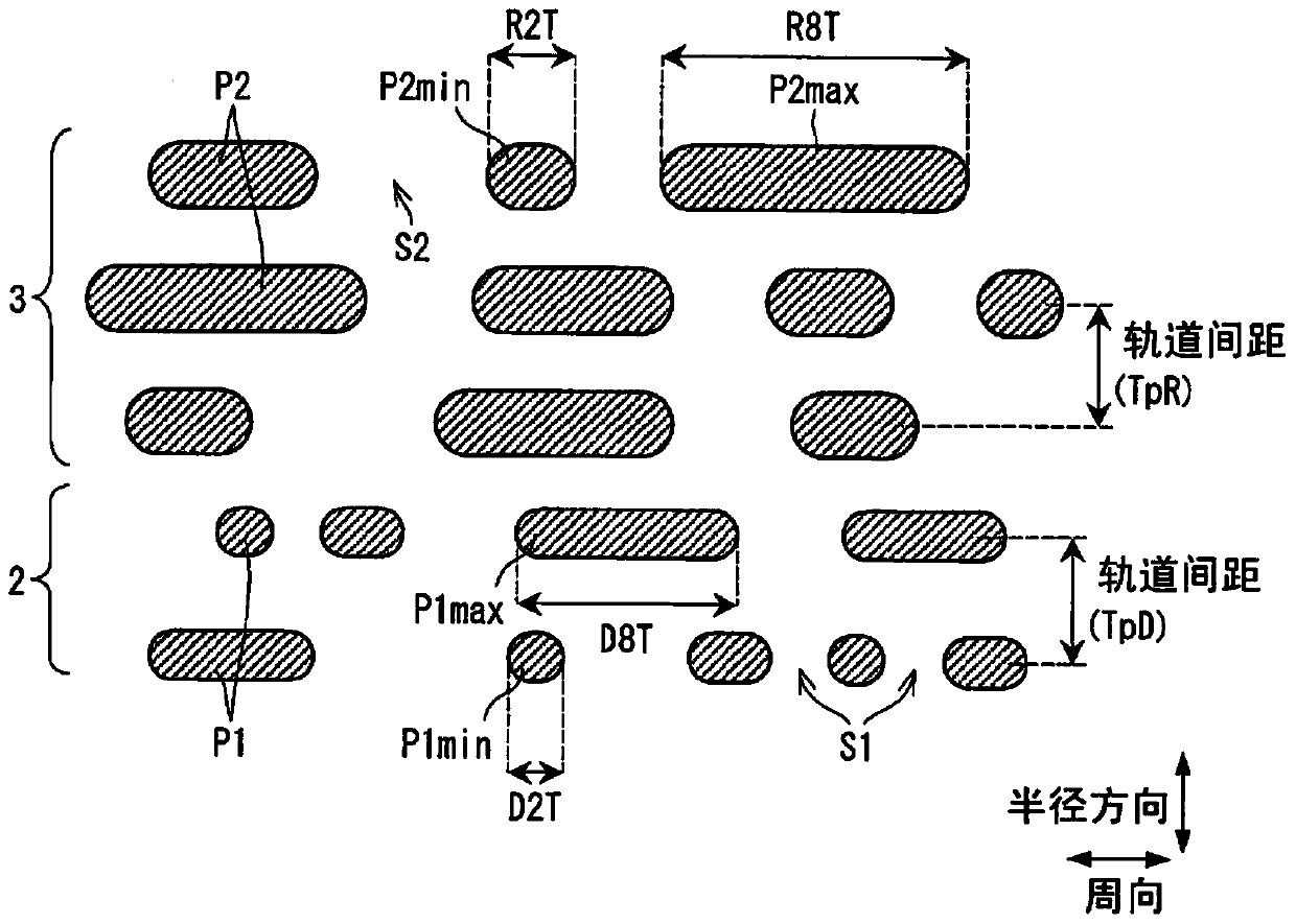
[0136] The super-resolution medium 1 according to this embodiment is similar to the embodiment in that the lengths of the pits P1 and the gaps S1 are shorter than the lengths of the pits P1 and the gaps S1 in Embodiment 1 corresponding to the pits P1 and the gaps S1. Method 1 is different. Other configurations (for example, the pit shape of the medium information region 3 , etc.) are the same as those of the first embodiment.
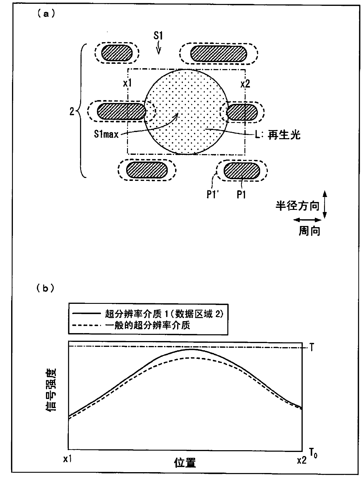
[0137] In this case, since the length of the longest gap S1max is shorter than the diameter of the irradiated region of the reproduction light L formed on the super-resolution medium 1, when the reproduction l...
Embodiment approach 3
[0167] Regarding another embodiment of the present invention, based on Figure 14 ~ Figure 15 Make the following description. In addition, for convenience of description, components having the same functions as those described in the above-mentioned embodiments are denoted by the same reference numerals, and description thereof will be omitted.
[0168] Figure 14 It is a diagram showing the polarity of the pits P1 and P2. like Figure 14 As shown, the super-resolution medium 1 of this embodiment differs from Embodiment 1 (recessed pit form) in that convex pits P1 and P2 are formed on the substrate 4 (formed as convex pits). Other configurations are the same as those of the first embodiment.
[0169] [Example]
[0170] Next, regarding an example of the super-resolution medium 1 of this embodiment, use Figure 15 Be explained. Figure 15 It is a diagram showing an example of the super-resolution medium 1, (a) is a diagram showing a state in which reproduction light L is ...
PUM
| Property | Measurement | Unit |
|---|---|---|
| wavelength | aaaaa | aaaaa |
| diameter | aaaaa | aaaaa |
| thickness | aaaaa | aaaaa |
Abstract
Description
Claims
Application Information