
Automated multi-station production line for disc parts

A disc-like parts and production line technology, applied in the field of automatic production equipment, can solve the problems of taking up a lot of space, material accumulation, and the need to change machine tools, etc., and achieve the effect of small time, zero inventory, and elimination of influence

Inactive Publication Date: 2016-01-27
YOUJI MACHINE IND CHINA COMPANY
View PDF9 Cites 13 Cited by
  • Summary
  • Abstract
  • Description
  • Claims
  • Application Information

AI Technical Summary

Problems solved by technology

[0002] The currently known and widely used processing method and equipment for disc parts are as follows: first, one side of the disc-shaped casting blank is rough-turned, and then the rough-turned side is used as a reference plane, and the other side of the face-changing car is used for punching and finishing. And other processing steps, each step must change the machine tool, or change the card on the same machine tool, or use the semi-automatic production line of disc parts, it is necessary to process the blanks in batches in advance to ensure sufficient supply of raw materials for each step of the production line, which will cause material loss. Accumulation requires a lot of space for storage, and it is impossible to achieve zero inventory in the production process, and the movement, clamping and unloading of materials between various machine tools requires manual operations, which invisibly maximizes the advantages of assembly line production Offset, and manual clamping is difficult to ensure the interchangeability of the same batch of products

Method used


Image

  • Automated multi-station production line for disc parts
  • Automated multi-station production line for disc parts
  • Automated multi-station production line for disc parts

Examples


Embodiment Construction

[0024] The present invention will be further described below in conjunction with the accompanying drawings.

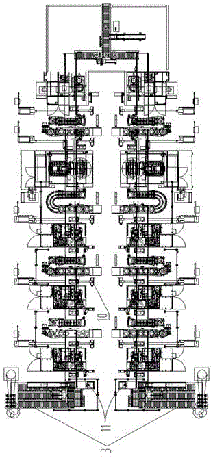
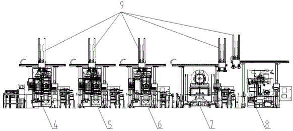
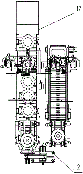
[0025] Such as Figures 1 to 4 As shown, the automatic multi-station production line for disk parts includes a logistics roller table system for connecting each processing unit of the production line. The logistics roller table system includes a workpiece turning device 2 for realizing automatic turning during material operation. On the surface, the feeding channel 3 is placed at the feeding position of the first numerically controlled lathe 4, and also includes the first numerically controlled lathe 4, the second numerically controlled lathe 5, and the third numerically controlled lathe 6 arranged in series. Afterwards, a machining center 7 and a double-sided lathe 8 are arranged in series, all of which are sequentially connected to other parts through a logistics roller table, and also include a truss manipulator system 9, which includes several The truss manipulato...


PUM


Abstract

An automated multi-station production line for disc parts comprises a logistics roller table system for connecting all machining units of the production line. The logistics roller table system comprises workpiece overturning devices, a NG material way and a discharging way. The production line further comprises a first numerical control lathe, a second numerical control lathe and a third numerical control lathe which are connected in series. The discharging way and a visual identification system are arranged on the feeding position of the first numerical control lathe. The three numerical control lathes are sequentially connected through the logistics roller table system. A machining center and a two-sided lathe are arranged behind and connected with the three numerical control lathes in series and connected with other parts through a logistics roller table in sequence. The production line further comprises a truss mechanical hand system. The truss mechanical hand system comprises multiple truss mechanical hands arranged above all machine tools on the production line. The workpiece overturning devices are arranged between the first numerical control lathe and the second numerical control lathe and between the second numerical control lathe and the third numerical control lathe respectively. Random sampling detection devices are arranged between every two machine tools.

Description

technical field [0001] The invention relates to an automatic production equipment for disc parts that need to be processed on both sides, in particular to an automatic production line for brake discs. Background technique [0002] The currently known and widely used processing method and equipment for disc parts are as follows: first, one side of the disc-shaped casting blank is rough-turned, and then the rough-turned side is used as a reference plane, and the other side of the face-changing car is used for punching and finishing. And other processing steps, each step must change the machine tool, or change the card on the same machine tool, or use the semi-automatic production line of disc parts, it is necessary to process the blanks in batches in advance to ensure sufficient supply of raw materials for each step of the production line, which will cause material loss. Accumulation requires a lot of space for storage, and it is impossible to achieve zero inventory in the pro...

Claims


Application Information

Patent Timeline
Patent Type & Authority Applications(China)
IPC IPC(8): B23B3/36B23B15/00
Inventor 凤为保余杰张向阳
Owner YOUJI MACHINE IND CHINA COMPANY
Learn More