Stone processing machine

A processing machine and stone technology, applied in stone processing equipment, stone processing tools, metal processing equipment, etc., can solve the problems of high labor cost, unstable product quality, low production efficiency, etc., and achieve good cleaning effect

Inactive Publication Date: 2016-01-27
重庆市永川区石包冲建材经营部
0 Cites 22 Cited by

AI-Extracted Technical Summary

Problems solved by technology

However, there are many disadvantages in this traditional operation method, which cannot well meet the survival and development needs of enterprises that are increasingly stimulated by competition.
Its main disadvantages are that the labor intensity of manual work is high and the production efficiency is low; the labor cost is high; limit...

Abstract

The invention provides a stone processing machine. The stone processing machine comprises a rack, a transverse polishing device, a vertical cutting device, a left water tank, a right water tank and a controller, wherein a servo motor and the controller are arranged at the upper end of the rack; the lower part of the controller is electrically connected with a right manipulator and a left manipulator; the vertical cutting device is arranged at the bottom of the right manipulator; the transverse polishing device is arranged at the bottom of the left manipulator; the left water tank and the right water tank are fixedly connected with the rack through left flushing spray pipes and right flushing spray pipes; and an electric rotary base is arranged in the rack. Compared with the prior art, the stone processing machine has the following beneficial effects: stone can be automatically cut or polished; and after stone is cut or polished, the controller controls the electric rotary base to rotate and meanwhile controls the right water tank and the left water tank to be opened, and further, the left flushing spray pipes and the right flushing spray pipes are enabled to spray a cleaning solution to clean stone, so that the cleaning effect is good.

Application Domain

Technology Topic

Image

  • Stone processing machine
  • Stone processing machine

Examples

  • Experimental program(1)

Example Embodiment

[0013] In order to make the technical means, creative features, objectives and effects of the present invention easy to understand, the present invention will be further explained below in conjunction with specific embodiments.
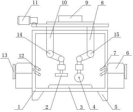
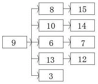
[0014] See figure 1 with figure 2 , The present invention provides a technical solution: a stone processing machine, comprising a frame 1, a horizontal grinding device 2, a vertical cutting device 4, a left water tank 13, a right water tank 6 and a controller 9, and the upper end of the frame 1 is provided with The servo motor 11 and the controller 9 are electrically connected to the right manipulator 8 and the left manipulator 10 under the controller 9. The bottom end of the right manipulator 8 is provided with a vertical cutting device 4, and the right manipulator 8 is provided with a right The joint controller 15 is provided with a vertical cutting device 4 at the bottom end of the left mechanical arm 10, a left joint controller 14 is provided on the left mechanical arm 10, and the left water tank 13 and the right water tank 6 are respectively installed on the left and right sides of the frame 1 The left water tank 13 and the right water tank are fixedly connected by the frame 1 through the left flushing nozzle 12 and the right flushing nozzle 7. The bottom of the frame 1 is provided with a base 5, and the inside of the frame 1 is provided with an electric rotating base Block 3.
[0015] The output terminal of the controller 9 is connected with the input terminal of the right mechanical arm 8, the output terminal of the right mechanical arm 8 is connected with the input terminal of the right joint controller 15, and the output terminal of the controller 9 is connected with the input terminal of the left mechanical arm 10. The output end of the left robotic arm 10 is connected to the input end of the left joint controller 14, the output end of the controller 9 is connected to the input end of the right water tank 6, and the output end of the right water tank 6 is connected to the input end of the right flushing nozzle 7, The output end of the controller 9 is connected to the input end of the left water tank 13, the output end of the left water tank 13 is connected to the input end of the left flushing nozzle 12, and the output end of the controller 9 is connected to the input end of the electric rotating base 3.
[0016] The staff can first place the stone to be processed on the electric rotating base 3, and then input the cutting path or the grinding path into the controller 9. The controller 9 will take out the spatial pose coordinate values ​​of each teaching point point by point, and through the alignment It performs linear or circular interpolation operations to generate the corresponding path plan, and then converts the pose coordinate value of each interpolation point into the joint angle value through the inverse kinematics calculation, and then adds it to the left joint controller 14 or the right joint control In the device 15, the horizontal grinding device 2 or the vertical cutting device 4 is further made to move according to the pre-input path to cut or polish the stone. After the horizontal grinding device 2 or the vertical cutting device 4 moves according to the pre-input path, The controller 9 will control the rotation of the electric rotating base 3, and at the same time control the opening of the right water tank 6 and the left water tank 13, so that the left flushing nozzle 7 and the right flushing nozzle 12 will spray cleaning liquid to clean the stone, because the stone is electric The rotating base 3 continuously rotates, so the left flushing nozzle 7 and the right flushing nozzle 12 can be cleaned more perfect and the cleaning effect is good.
[0017] The above shows and describes the basic principles and main features of the present invention and the advantages of the present invention. For those skilled in the art, it is obvious that the present invention is not limited to the details of the above exemplary embodiments, and does not deviate from the spirit or basics of the present invention. In the case of features, the present invention can be implemented in other specific forms. Therefore, from any point of view, the embodiments should be regarded as exemplary and non-limiting. The scope of the present invention is defined by the appended claims rather than the foregoing description, and therefore it is intended to fall within the claims. All changes within the meaning and scope of equivalent elements of are included in the present invention. Any reference signs in the claims should not be regarded as limiting the claims involved.
[0018] In addition, it should be understood that although this specification is described in accordance with the embodiments, not every embodiment only includes an independent technical solution. This narration in the specification is only for clarity, and those skilled in the art should consider the specification as a whole The technical solutions in the embodiments can also be appropriately combined to form other implementations that can be understood by those skilled in the art.

PUM

no PUM

Description & Claims & Application Information

We can also present the details of the Description, Claims and Application information to help users get a comprehensive understanding of the technical details of the patent, such as background art, summary of invention, brief description of drawings, description of embodiments, and other original content. On the other hand, users can also determine the specific scope of protection of the technology through the list of claims; as well as understand the changes in the life cycle of the technology with the presentation of the patent timeline. Login to view more.

Similar technology patents

Surface cleaning equipment

ActiveCN103705179AReduce noiseGood cleaning effectFloor sweeping machinesScrub brushesEngineering
Owner:SUZHOU CHENGHE CLEANING EQUIP

Classification and recommendation of technical efficacy words

Why Eureka
Try Eureka