Line light spot optical lighting system based on cylindrical surface array

A lighting system and optical technology, applied in the direction of lighting devices, lighting and heating equipment, parts of lighting devices, etc., can solve problems such as inability to achieve brightness uniformity, and achieve good edge sharpness, easy processing, and simple exit surface Effect

Inactive Publication Date: 2016-01-27
戴朝卿
View PDF8 Cites 6 Cited by
  • Summary
  • Abstract
  • Description
  • Claims
  • Application Information

AI Technical Summary

Problems solved by technology

Existing illumination optical systems cannot achieve a l

Method used


Image

  • Line light spot optical lighting system based on cylindrical surface array
  • Line light spot optical lighting system based on cylindrical surface array
  • Line light spot optical lighting system based on cylindrical surface array

Examples


Embodiment Construction

[0022] The present invention will be described in detail below in conjunction with specific embodiments.

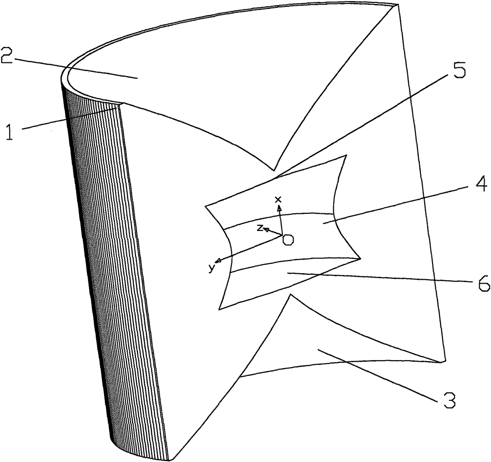
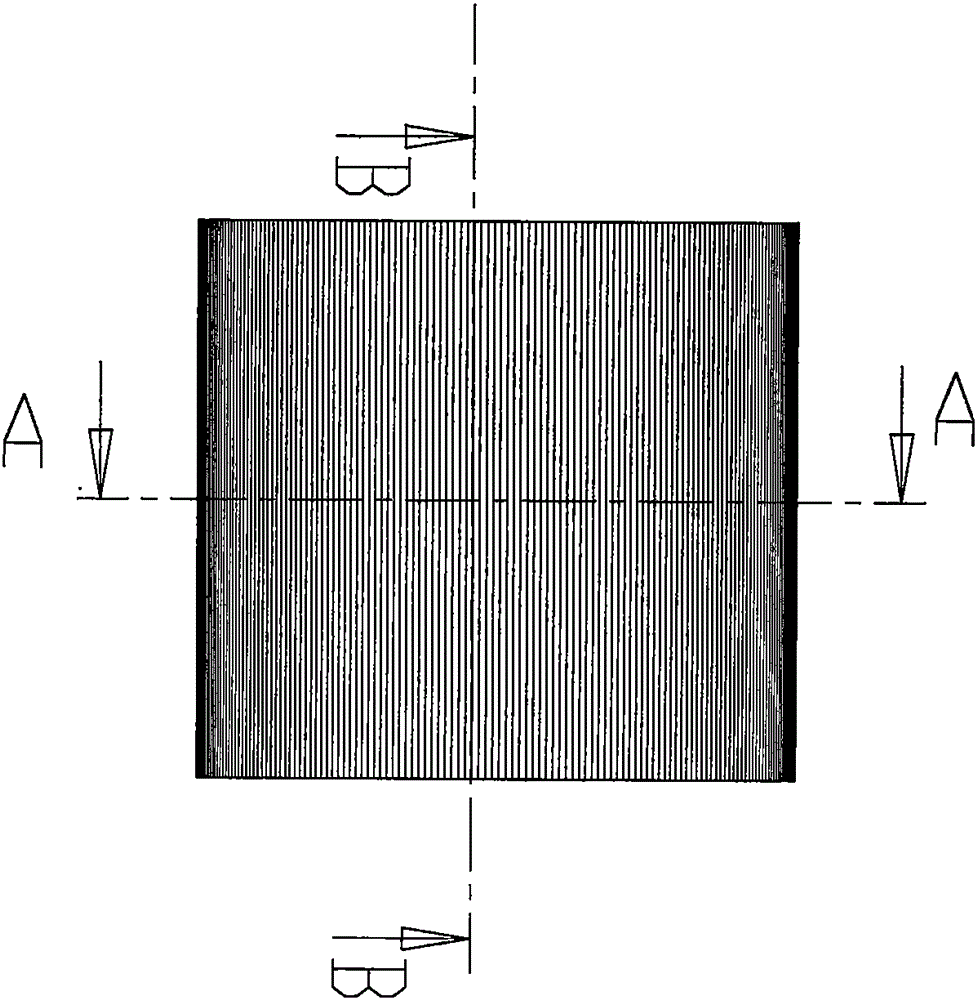
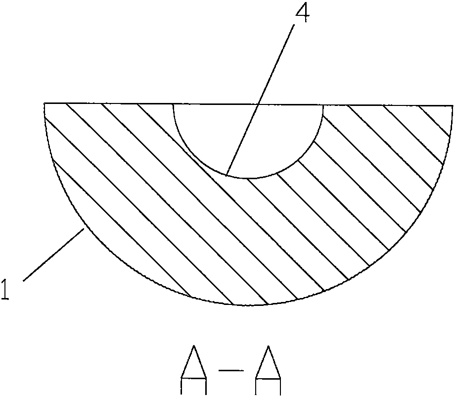
[0023] The optical illumination system based on the line spot of the cylindrical array, the overall shape is a semi-cylinder, and the inside of the semi-cylinder is a closed space containing the light source O. The walls of the closed space are respectively: the saddle-shaped incident surface 4 located directly in front of the light source. , The first semi-conical incident surface 5 and the second semi-conical incident surface 6 located above and below the light source; the periphery of the enclosed space includes a cylindrical exit surface 1 located directly in front of the enclosed space and the enclosed space The first total reflection arc surface 2 and the second total reflection arc surface 3 on the upper and lower portions.

[0024] reference Figure 1-Figure 5 , Take the position of the light source O as the coordinate system circle point, the bottom plane (installati...


PUM


Abstract

The invention discloses a line light spot optical lighting system based on a cylindrical surface array. The wall faces of closed space for containing a light source O include a saddle-shaped incidence face (4) located right in front of the light source, a first semicircular cone face incidence face (5) and a second semicircular cone face incidence face (6), and the first semicircular cone face incidence face (5) and the second semicircular cone face incidence face (6) are located above and below the light source. A half-cylindrical-face emitting face (1) located right in front of the closed space, a first total reflection camber surface (2) and a second total reflection camber surface (3) are arranged on the periphery of the closed space, wherein the first total reflection camber surface (2) and the second total reflection camber surface (3) are located at the upper portion and the lower portion of the closed space. The emitting face (1) is formed in the manner that a plurality of strip-shaped cylindrical mirror units are distributed along the half cylindrical face in an array manner one by one, and the strip-shaped cylindrical mirror units have the gathering function on light rays. Obtained line light spots are fine and narrow in distribution; and in addition, the margin sharpness is good, light bands are evenly distributed, and the line light spot optical lighting system is suitable for indoor and outdoor decorative lighting occasions.

Description

Technical field [0001] The invention relates to an optical lighting system, in particular to an optical lighting system based on a cylindrical array of line spots, which is suitable for external wall facades, doors and windows, corridors or indoor decoration lighting occasions. Background technique [0002] The line spot can be applied to various occasions that outline a straight line, and at the same time realize the light and shadow weaving of light, and bring people a variety of light and shadow artistic effects. The existing illumination optical system cannot achieve a narrow width of the line spot of brightness uniformity. Therefore, the prior art has defects and needs to be improved. Summary of the invention [0003] The purpose of the present invention is to overcome the above-mentioned shortcomings and provide an optical illumination system based on a cylindrical array of line spots, which emits light at a maximum angle in one direction (in the present invention at 120-18...

Claims


Application Information

Patent Timeline
IPC IPC(8): F21S2/00F21V5/00F21V7/09
CPCF21S2/00F21V5/00F21V7/09
Inventor 戴朝卿陈瑞品
Owner 戴朝卿
Why Eureka
Try Eureka