Light irradiation device
A technology of light irradiation device and irradiation surface, which is applied to lighting devices, cooling/heating devices of lighting devices, lighting and heating equipment, etc., can solve problems such as profound, reduced luminous efficiency and lifespan, and achieve the effect of less temperature difference
- Summary
- Abstract
- Description
- Claims
- Application Information
AI Technical Summary
Problems solved by technology
Method used
Image
Examples
no. 1 Embodiment
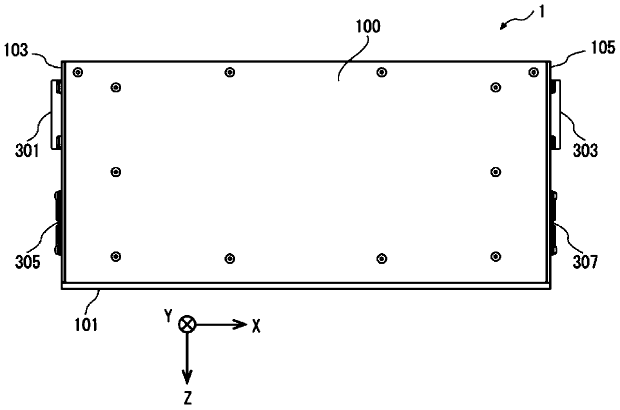
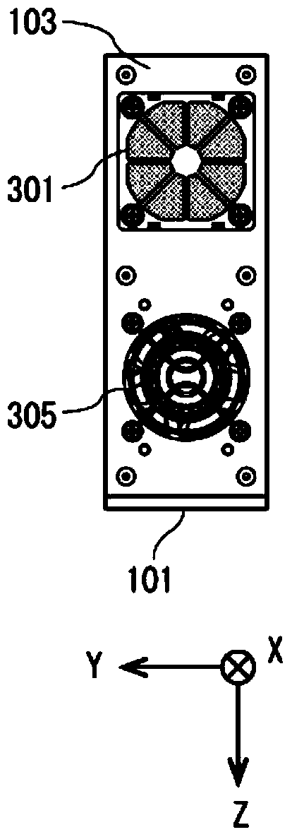
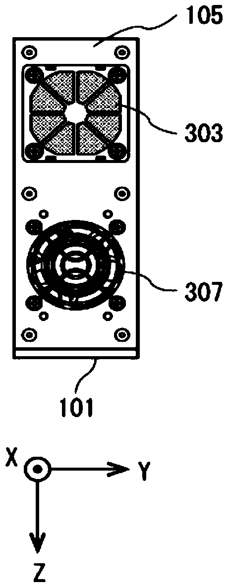
[0064] Figure 1 to Figure 4 An external view illustrating the structure of the light irradiation device according to the first embodiment of the present invention, Figure 1 ~ Figure 4 These are respectively a plan view, a left side view, a right side view, and a front view of the light irradiation device 1 according to the first embodiment of the present invention. also, Figure 5 to Figure 7 A schematic diagram illustrating the internal structure of the light irradiation device 1 according to the first embodiment of the present invention, Figure 5 It is a figure showing the appearance when the outer casing of the light irradiation device 1 is removed, Figure 6 for use Figure 5 A longitudinal sectional view cut along line A-A of Figure 7 for Figure 5 cross-sectional view of . The light irradiation device 1 of this embodiment is a device mounted on a printing device that uses UV ink that is hardened by irradiation of ultraviolet light to print, and is arranged oppo...
no. 2 Embodiment
[0093] Figure 10 It is a cross-sectional view of a light irradiation device 1A according to a second embodiment of the present invention. Such as Figure 10 As shown, the air intake fans 301A and 303A of the cooling device 300A of the light irradiation device 1A of the present embodiment are respectively installed in the opening 310da formed in the back panel 310d and the opening 310ea formed in the back panel 310e, and the direction of sucking air from the outside is The Z-axis direction is different from the light irradiation device 1 of the first embodiment in this point.
[0094] In this embodiment, air from the outside is sucked into the space R1U (or R2U) by the suction fan 301 (or 303 ), and rectified in the space R1U (or R2U). Then, the air in the space R1U (or R2U) is sent into the space R1L (or R2L), passes between the cooling fins 213 arranged in the space R1L (or R2L), and is exhausted to the outside by the exhaust fan 305 (or 307). gas. Therefore, through the...
no. 3 Embodiment
[0096] Figure 11 It is a cross-sectional view of a light irradiation device 1B according to a third embodiment of the present invention. Such as Figure 11 As shown, the light irradiation device 1B of this embodiment divides the space in the wind tunnel housing 310B of the cooling device 300B into four spaces R1, R2, R3, and R4 along the X-axis direction through three partitions 310c, forming a A structure for cooling the spaces R1, R2, R3, and R4 respectively (that is, a structure with four cooling mechanisms), which is different from the light irradiation device 1 according to the first embodiment and the light irradiation device according to the second embodiment. 1A is different. Furthermore, the three spacers 310c of this embodiment are respectively divided between the second row of cooling fins 213 and the third row of cooling fins 213 from the left side, and between the fourth row of cooling fins 213 and the fifth row of cooling fins. Between the heat dissipation fi...
PUM
 Abstract
Description
Claims
Application Information
 - R&D
- Intellectual Property
- Life Sciences
- Materials
- Tech Scout
- Unparalleled Data Quality
- Higher Quality Content
- 60% Fewer Hallucinations
Browse by: Latest US Patents, China's latest patents, Technical Efficacy Thesaurus, Application Domain, Technology Topic, Popular Technical Reports.
© 2025 PatSnap. All rights reserved.Legal|Privacy policy|Modern Slavery Act Transparency Statement|Sitemap|About US| Contact US: help@patsnap.com


