A heat-conducting and heat-dissipating plate assembly for a heating heat exchanger with a tube-row structure

A heating heat exchanger and heat sink technology, applied in the direction of heat exchanger types, indirect heat exchangers, fixed conduit components, etc., can solve the problems that affect the user's recognition of products, small heating and heat dissipation area, monotonous appearance, etc. Excellent heat exchange performance and heat dissipation performance, heating effect improvement, beautiful appearance effect

Active Publication Date: 2016-10-19
ZAOZHUANG FUYUAN ENVIRONMENTAL PROTECTION & ENERGY SAVING MACHINERY MFG CO LTD
View PDF7 Cites 0 Cited by
  • Summary
  • Abstract
  • Description
  • Claims
  • Application Information

AI Technical Summary

Problems solved by technology

Using this kind of heating heat exchanger, while providing domestic hot water for users, it can also provide heating for the local environment through its outer surface, especially the outer surface of the circular tube, but its heating and heat dissipation area is obviously smaller than that of radiators. , especially when the heating heat exchanger continuously releases a large amount of hot water, the tap water flowing through the heat exchanger has no time to rise to the temperature close to the heating system, and its heating effect drops significantly
In addition, the welded structure and the pressure bearing effect of the material are mainly considered when combining pipe rows. Therefore, the appearance is monotonous and inconsistent with the environment, which affects the user's approval of the product

Method used


Image

  • A heat-conducting and heat-dissipating plate assembly for a heating heat exchanger with a tube-row structure
  • A heat-conducting and heat-dissipating plate assembly for a heating heat exchanger with a tube-row structure
  • A heat-conducting and heat-dissipating plate assembly for a heating heat exchanger with a tube-row structure

Examples


Embodiment Construction

[0021] Describe the present invention in detail below in conjunction with accompanying drawing and embodiment.

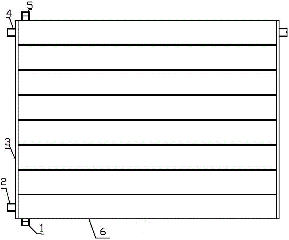
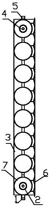
[0022] Such as figure 1 , figure 2 Shown: a combination of heat conduction and heat dissipation plates for a heating heat exchanger with a tube row structure. Its tube row structure includes a plurality of parallel arranged round tubes, for example figure 2 7 in the middle, its diameter can be 76, 85, 90 millimeters etc., quantity is like 6, 8, also includes the communication device that can be arranged on the two ends of round tube 7 and can connect each round tube fixedly into the shape of tube row, communication device It is usually round tube, D-shaped, mouth-shaped, and the special-shaped shape (combined by connecting pipe, connecting pipe and round pipe head) in the inventor's two existing invention patents. The round pipe 7 and the communicating device All adopt thin-walled stainless steel materials, and the radiator of this pipe row structure is also pro...


PUM


Abstract

The invention discloses a heat-conducting and heat-dissipating plate assembly for a heating heat exchanger with a pipe row structure. The connecting device fixedly connected in the shape of a tube row, the circular tube and the connecting device are made of thin-walled stainless steel, and on the outer surface of the circular tube in the forward direction, there are heat-conducting and heat-dissipating plates arranged in parallel along the length direction of the circular tube to conduct heat. The front of the heat dissipation plate faces outward, and the back has an arc surface and closely matches the outer surface of the round tube. The number, length, width and thickness of the heat conduction and heat dissipation plates match the round tube. The present invention also includes covering communication devices arranged at both ends of the round tube The two positioning and clamping end caps, the front edge of the positioning and clamping end cap is buckled and pressed on the front of the heat conduction and heat dissipation plate, the rear edge of the positioning and tightening end cap is buckled and pressed on the outer surface of the circular tube adjacent to the communication device, and the positioning is tightened The end cover is also provided with a detachable connecting device fastened with the pipe row structure.

Description

technical field [0001] The invention belongs to the technical field of civil heating, and in particular relates to a heat conduction and heat dissipation plate assembly for a heating heat exchanger with a pipe row structure, which is closely related to the heating heat exchanger with a pipe row structure made of thin-walled stainless steel. Background technique [0002] In the field of civil heating technology, the heating heat exchanger of the pipe row structure is composed of two inner and outer passages that are not connected to each other, such as the heating inlet and outlet channels and the tap water inlet and outlet channels. The inlet of the running water inlet and outlet passage provided outside the row structure is connected with the running water pipe, and the outlet outputs hot water. From the perspective of the external shape, it mainly includes a plurality of circular tubes arranged in parallel, and also includes a communication device arranged at both ends of ...

Claims


Application Information

Patent Timeline
Patent Type & Authority Patents(China)
IPC IPC(8): F28D1/053F28F1/12
Inventor 孙有福孙淑慧陆郝凌
Owner ZAOZHUANG FUYUAN ENVIRONMENTAL PROTECTION & ENERGY SAVING MACHINERY MFG CO LTD
Why Eureka
Try Eureka