Dynamic noncontact rail gauge measuring system and method thereof

A measurement system and track gauge technology, applied in the direction of measuring devices, instruments, optical devices, etc., can solve the problems of affecting measurement accuracy, limitations, complex equipment of photoelectric measurement methods, etc., and achieve the effect of improving detection speed

Active Publication Date: 2016-01-27
北京星网宇达科技股份有限公司
View PDF5 Cites 19 Cited by
  • Summary
  • Abstract
  • Description
  • Claims
  • Application Information

AI Technical Summary

Problems solved by technology

[0002] At present, the rail transit system generally uses the gauge ruler to measure the gauge in the process of track construction acceptance and routine maintenance. On the portable rail inspection vehicle, the linear displacement sensor is generally used for contact measurement. The traditional contact measurement method requires the measuring probe and The measured surface of the rail is in close contact, which will bring a series of problems, such as: the measurement accuracy is affected by the wear of the measuring probe or the rail, the problem that the probe cannot touch the measured surface of the rail due to the fat edge of the rail, and the probe cannot be guaranteed due to various factors. The problem of deviation from pointing to the measured point and the inability to meet the requirements of high-speed measurement, the method of measuring track gauge using linear displacement sensor contact is limited in the field of high-speed dynamic gauge measurement
[0003] In recent years, modern large-scale track inspection vehicles have been researched and equipped at home and abroad, equipped with advanced photoelectric measurement methods for gauge measurement. However, the photoelectric measurement method equipment is complex and expensive, and it will be greatly affected when used in track construction acceptance and routine maintenance. limit

Method used


Image

  • Dynamic noncontact rail gauge measuring system and method thereof
  • Dynamic noncontact rail gauge measuring system and method thereof
  • Dynamic noncontact rail gauge measuring system and method thereof

Examples


Embodiment Construction

[0033] The present invention will be described in further detail below in conjunction with the accompanying drawings.

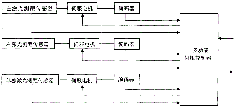
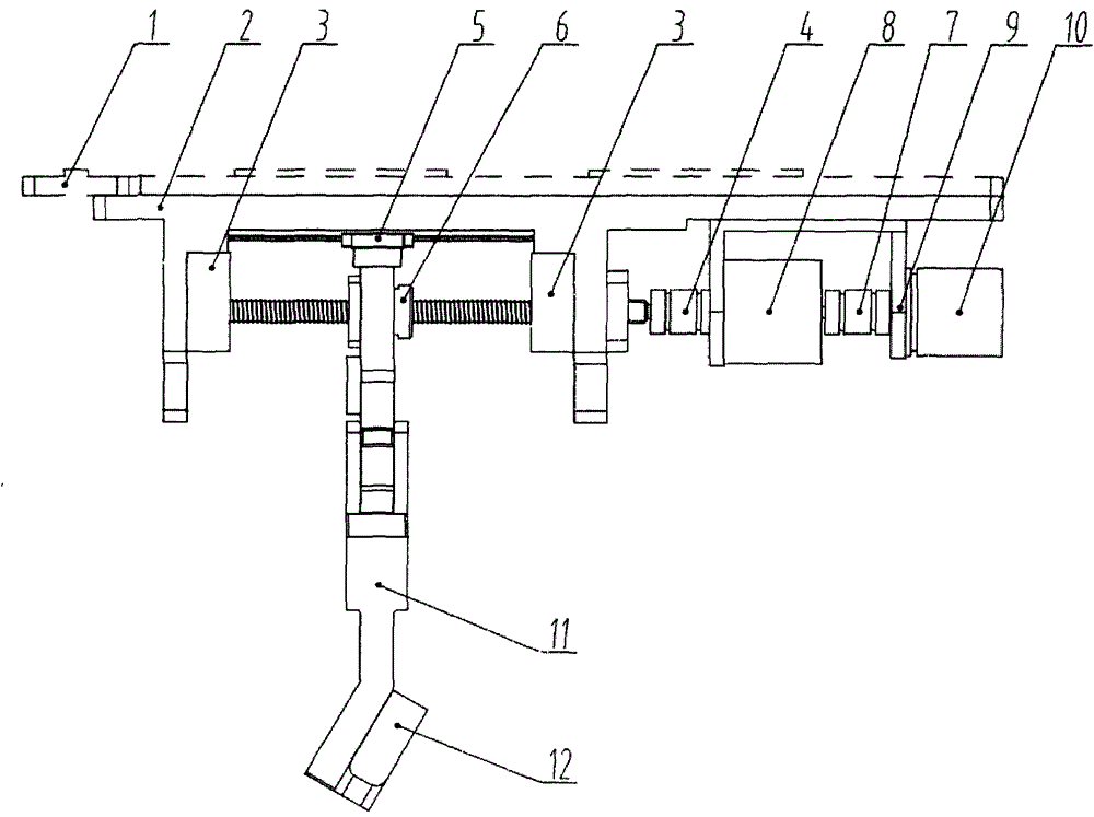
[0034] In this example, if figure 1 The principle block diagram of the track gauge measurement system is shown. The laser distance measuring sensor dynamic non-contact track gauge measurement system and its method are composed of three identical track gauge measurement components and a multifunctional servo that can simultaneously control the three same track gauge measurement components. The controller component constitutes. Each gauge measurement component includes: component base 1, guide rail seat 2, left and right limit stops 3, torque servo motor coupling 4, linear guide rail 5, lead screw 6, encoder coupling 7, torque Servo motor 8, motor bracket 9, encoder 10, laser ranging sensor moving bracket 11, laser ranging sensor 12.

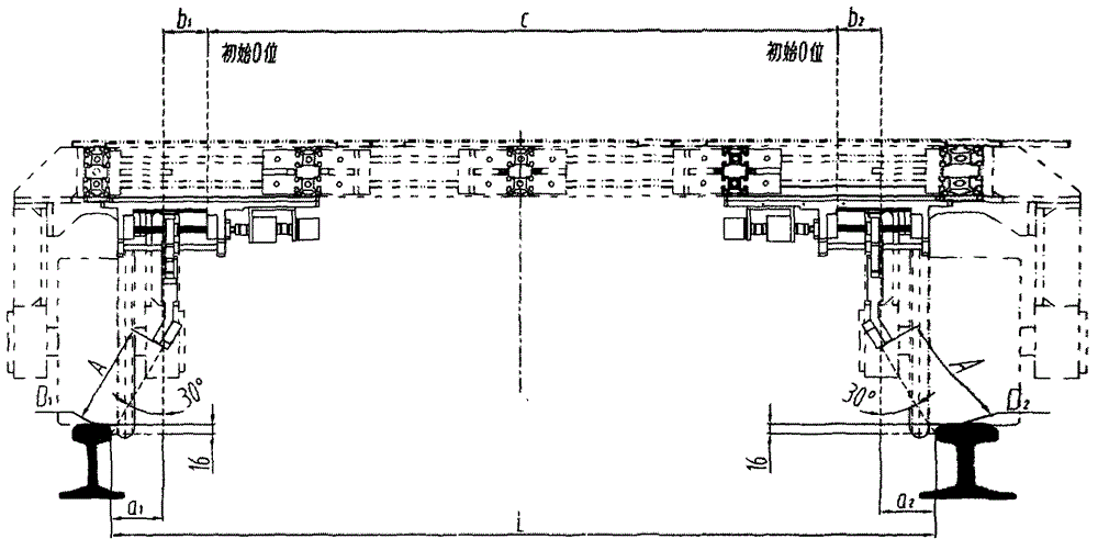
[0035] According to the physical and mathematical model determined by the track gauge measurement system and its method, the...


PUM


Abstract

The invention discloses a dynamic noncontact rail gauge measuring system and a method thereof. The dynamic noncontact rail gauge measuring system based on a laser ranging sensor of the triangulation principle is composed of three identical gauge measuring components and a multifunctional servo controller component capable of controlling the three identical gauge measuring components simultaneously. The dynamic noncontact rail gauge measuring system and the method thereof are used for a rail parameter dynamic detection trolley to realize noncontact gauge measurement, the highest detection speed can be 60kg / h and measuring precision can be + / -0.2m so that the dynamic noncontact rail gauge measuring system and the method thereof have a function of correcting heading direction of a high-speed rail inspection trolley, and are simple in structure, high in stability of the measuring result and favorable for popularization and application on various rail inspection trolleys.

Description

technical field [0001] The invention relates to a track gauge detection system and a method thereof, in particular to a dynamic non-contact track gauge measurement system and a method thereof. Background technique [0002] At present, the rail transit system generally uses the gauge ruler to measure the gauge in the process of track construction acceptance and routine maintenance. On the portable rail inspection vehicle, the linear displacement sensor is generally used for contact measurement. The traditional contact measurement method requires the measurement probe and The measured surface of the rail is in close contact, which will bring a series of problems, such as: the measurement accuracy is affected by the wear of the measuring probe or the rail, the problem that the probe cannot touch the measured surface of the rail due to the fat edge of the rail, and the probe cannot be guaranteed due to various factors. Due to the problem of deviation from the point to be measure...

Claims


Application Information

Patent Timeline
Patent Type & Authority Applications(China)
IPC IPC(8): G01B11/14
Inventor 迟家升
Owner 北京星网宇达科技股份有限公司
Why Eureka
Try Eureka