Method for designing optimal back zone draft ratio of drawing frame

A technology of drafting ratio and drawing frame, which is applied in the direction of applying stable tension/pressure to test the strength of materials, etc., can solve the problems of high cost, complicated equipment and operation, and achieve the effect of saving raw materials and accurate methods

Inactive Publication Date: 2016-01-27
DONGHUA UNIV
View PDF3 Cites 2 Cited by
  • Summary
  • Abstract
  • Description
  • Claims
  • Application Information

AI Technical Summary

Problems solved by technology

However, this device still needs to use raw materials to test on the draw frame to determine the optimal draft ratio in the rear area. The device and operation are very complicated and the cost is high

Method used


Image

  • Method for designing optimal back zone draft ratio of drawing frame
  • Method for designing optimal back zone draft ratio of drawing frame
  • Method for designing optimal back zone draft ratio of drawing frame

Examples


Embodiment 1

[0041] It is planned to draw the carded cotton sliver (the weight of a single cotton sliver is 2.39g / m), and the combined number is 6. According to the length of the fiber and other properties, the center distance of the rollers in the rear area of ​​the draw frame is set to 50mm , it is now necessary to determine the optimal draft ratio in the back zone.

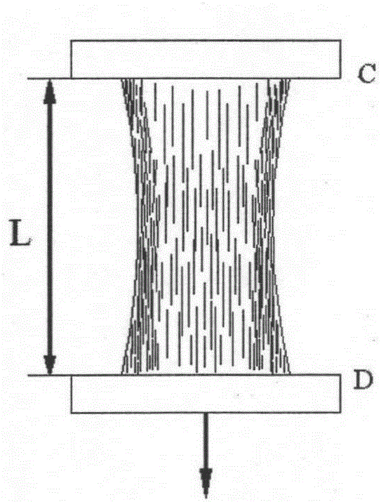
[0042] Firstly, the dynamic drafting is simulated by static stretching. The static drafting is to use the stretching tester to hold the two ends of the sliver respectively, and stretch the cotton sliver at a certain speed to simulate the drafting. The optimal stretching curve is determined according to the stretching curve. The draft ratio of the optimal back zone.

[0043] Stretch 6 cotton slivers (total weight 14.34g / m) on a universal material testing machine, set the clamping distance of the upper and lower chucks to 50mm, and obtain the experimental values ​​of critical tensile force and critical elongation and Tensile...

Embodiment 2

[0049] It is planned to draw the carded cotton sliver (the weight of a single cotton sliver is 2.28g / m), and the number of combined roots is 8. According to the length of the fiber and other properties, the center distance of the rollers in the rear area of ​​the drawing frame is set to 46.6 mm, it is now necessary to determine the draft multiple of the rear area.

[0050] Tensile test was used to stretch 8 cotton slivers (total weight: 19.08g / m), set the clamping distance of the upper and lower chucks to 46.6mm, and obtain the experimental values ​​of critical tensile force and elongation And tensile force and elongation curves are shown in Table 2 and Figure 8 shown.

[0051] Table 2 The maximum tensile force and critical elongation of eight cotton slivers

[0052] Testing frequency

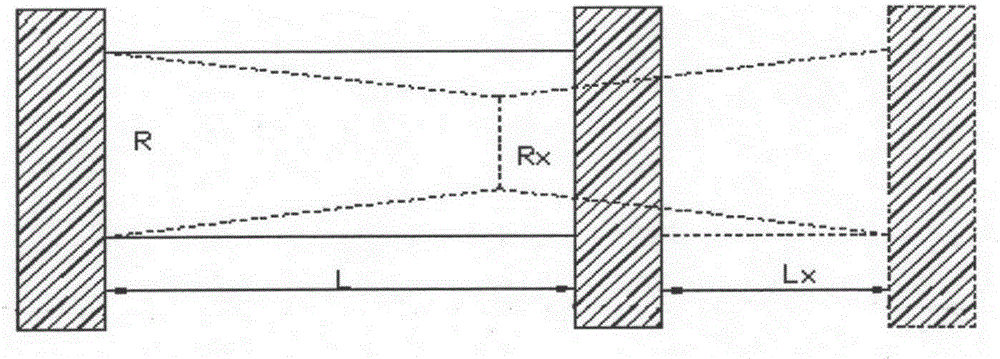
[0053] use the formula Where L is the clamping distance, L x For stretch elongation. Convert the elongation into the draw ratio, and obtain the relationship curve between the ...

Embodiment 1

[0054] Embodiment 1 verification example

[0055] On the DHUA301 drawing frame, feed the sliver with a total weight of 14.31g / m, set the center distance of the rollers in the rear drafting area to 50mm, and set the drafting ratios in the rear area to 1.462, 1.52, 1.583, and 1.652 respectively for drafting Test the force, and measure the CV value of the evenness of the combined sliver on the YG139BA evenness tester. Obtain the experimental data of the draft ratio in the rear area and the draft force and the evenness CV value as shown in table 3, and make the relationship curve between the draft ratio in the rear area and the draft force according to the data in the table Figure 10 shown.

[0056] Table 3 Experimental data of drafting force and evenness CV value under different drafting ratios

[0057] Number of teeth

26

25

24

23

Draft multiples in back zone

1.462

1.52

1.583

1.652

Drawing force(cN)

110.67

127.08 ...


PUM


Abstract

The invention provides a method for designing the optimal back zone draft ratio of a drawing frame. The method comprises the steps that an upper chuck and a lower chuck of a drawing tester clamp the two ends of a fiber fringe to conduct drawing, the fringe between the upper chuck and the lower chuck is drafted and drawn to be thin and long till the middle of the fringe is completely separated along with the process of drawing, and when the drawing force is the largest, the corresponding draft ratio is the optimal back zone draft ratio of the drawing frame. According to the method for designing the optimal back zone draft ratio of the drawing frame, static drawing of the drawing tester is adopted to simulate dynamic drawing, according to a relation curve of simulated drawing force and extension, the extension is converted into the draft ratio through a formula, the extension corresponding to the maximum value of the drawing force can have the maximum drawing force, evenness of sliver is minimum at this time, and therefore the draft ratio corresponding to the maximum value of the drawing force is the optimal draft ratio of a back draft zone. The method for designing the optimal back zone draft ratio of the drawing frame is simple, practical and capable of saving time, labor and raw materials, and the simple, effective and accurate method is provided for design of the back zone draft ratio of the drawing process.

Description

technical field [0001] The invention belongs to the technical field of textiles, and in particular relates to providing a simple and effective design method for the optimal draft ratio in the back zone of a draw frame. Background technique [0002] The drafting of the draw frame is an important step in the spinning process, and it has a very close relationship with the quality of the yarn, especially the reasonable determination of the draft multiple in the rear area is very critical to the quality of the output product. There is a corresponding relationship between the draft ratio and the draft force, but under different raw material properties (such as fiber length, fineness and type, etc.) and processes (such as draft gauge, etc.), the relationship between the draft ratio and the draft force will also be different. Different draft ratios in the back zone have a direct impact on the evenness of the output sliver. Therefore, during processing, the draft ratio in the rear z...

Claims


Application Information

Patent Timeline
Patent Type & Authority Applications(China)
IPC IPC(8): G01N3/08
Inventor 高志娟张一帆关赛鹏郁崇文
Owner DONGHUA UNIV
Why Eureka
Try Eureka