
Liquid crystal wave plate birefringent filter

A technology of birefringence filters and liquid crystal wave plates, applied in optics, instruments, optical components, etc., can solve problems such as lack of equipment

Active Publication Date: 2016-01-27
NAT ASTRONOMICAL OBSERVATORIES CHINESE ACAD OF SCI
View PDF3 Cites 2 Cited by
  • Summary
  • Abstract
  • Description
  • Claims
  • Application Information

AI Technical Summary

Problems solved by technology

[0006] The purpose of the present invention is to provide a liquid crystal wave plate birefringence filter to solve the problem of lack of equipment using photoelectric modulation in the prior art, to achieve a birefringence filter with small volume, accurate beam propagation, and convenient crystal phase structure change device

Method used

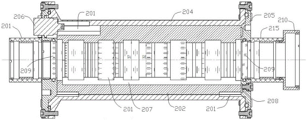
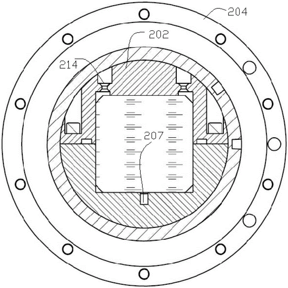

Image

  • Liquid crystal wave plate birefringent filter
  • Liquid crystal wave plate birefringent filter
  • Liquid crystal wave plate birefringent filter

Examples


Embodiment Construction

[0022] The technical solutions of the present invention will be described in further detail below with reference to the accompanying drawings and embodiments.

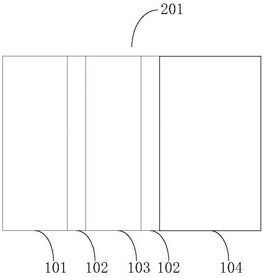
[0023] figure 1 A schematic diagram of a liquid crystal wave plate of a Lyot structure provided by the embodiment of the present invention, as figure 1 As shown, it consists of a polarizer 101, Iceland stone 102, H-1 / 2 wave plate 103, and LCVR-liquid crystal wave plate 104. The Lyot structure provided by the embodiment of the present invention is arranged in order from left to right as P-polarizer 101, B-Iceland stone 102, H-1 / 2 wave plate 103, B-Iceland stone 102, LCVR-liquid crystal wave plate 104. The thickness of each layer of the structure is different according to different usage requirements, but its layer structure will not change. In the embodiment of the present invention, for the convenience of description, the liquid crystal wave plate with Lyot structure is collectively referred to as crystal 201 .

[...


PUM


Abstract

The invention relates to a liquid crystal wave plate birefringent filter comprising a crystal base, end covers, and a sleeve. The crystal base internally includes a crystal cavity for arranging crystals, and the crystals are of a multi-stage Lyot structure in the crystal cavity and are axially arranged in a penetrating manner. The sleeve is arranged outside the crystal cavity, and the two ends of the sleeve are each equipped with one end cover for sealing. The end covers are each equipped with a vacuum socket which includes an electrode line connected to the crystals. A diversion trench is arranged in the crystal cavity, the gaps between the diversion trench and the crystals and the gaps between the crystal cavity and the crystals are filled with silicone oil, and the inner side of each end cover is provided with an oil storage chamber communicated with the diversion trench. The vacuum sockets each include an electrode line, and the crystal structure is changed through current to achieve the purpose of phase delay. The diversion trench for silicone oil circulation is arranged in the crystal cavity, and the gaps between the crystals are filled with silicone oil, so that the refractive index is not affected because of the gaps between the crystals. When the silicone oil expands due to temperature rise, the silicone oil can be flowed to the oil storage chamber to alleviate their situation.

Description

technical field [0001] The invention relates to the technical field of solar observation equipment, in particular to a liquid crystal wave plate birefringence filter. Background technique [0002] With the deepening of solar physics research, the requirements for the wavelength band, viewing angle and resolution of solar observation have also increased. With the development of the times, traditional ground-based observations are constantly updating equipment, improving image processing methods, and enhancing ground-based observation capabilities. However, due to the influence of the earth's atmospheric absorption, disturbance, background radiation and observation base environment such as weather, it is gradually difficult to meet the increasing observation requirements. Compared with traditional ground-based observations, space observations have unmatched advantages in terms of observation frequency bands, spatial and energy resolution limits, and observable time periods. ...

Claims


Application Information

Patent Timeline
IPC IPC(8): G02B5/24
CPCG02B5/24
Inventor 张洋王东光孙文君
Owner NAT ASTRONOMICAL OBSERVATORIES CHINESE ACAD OF SCI
Learn More