Fusion reaction hot spot area proton imaging method, calibration device and experiment device

A proton imaging and fusion reaction technology, applied in the fields of fusion particle diagnosis and beam optics, can solve problems such as digital noise, and achieve the effect of eliminating image blur, solving aiming difficulties and small size

Active Publication Date: 2016-01-27
LASER FUSION RES CENT CHINA ACAD OF ENG PHYSICS
View PDF3 Cites 9 Cited by
  • Summary
  • Abstract
  • Description
  • Claims
  • Application Information

AI Technical Summary

Problems solved by technology

And since it needs to encode and deco...

Method used


Image

  • Fusion reaction hot spot area proton imaging method, calibration device and experiment device
  • Fusion reaction hot spot area proton imaging method, calibration device and experiment device

Examples


Embodiment 1

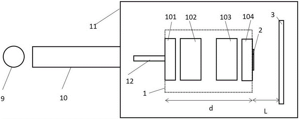
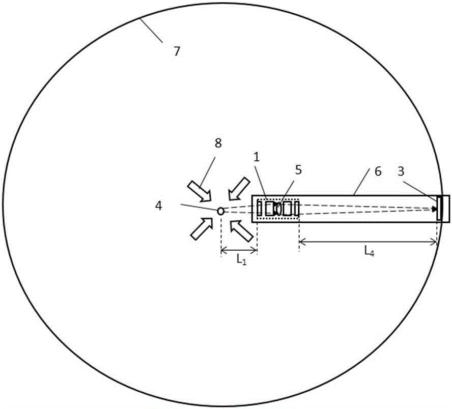
[0039] figure 1 It is a schematic diagram of the calibration device of the fusion reaction hot spot area proton imaging method in the present invention; figure 2 It is a schematic diagram of the experimental device of the proton imaging method in the fusion reaction hot spot area in the present invention.

[0040] The fusion reaction hot spot area proton imaging method of the present invention comprises the following steps:

[0041] a. Carry out the calibration of the micro-magnetic quadrupole lens for proton imaging in the calibration device;

[0042] b. Set the object distance and image distance of the miniature magnetic quadrupole lens in the experimental device;

[0043] c. Perform equivalent optical lens aiming in the experimental device;

[0044] d. Perform experimental diagnostics in the experimental setup.

[0045] figure 1 The calibration device in the fusion reaction hot spot region proton imaging method includes a tandem electrostatic accelerator 9, a proton tra...

Embodiment 2

[0066] Example 2 is for D 3 Designed for the 14.7MeV proton of the He reaction. In embodiment 2, the magnet strength is the same as in embodiment 1, and all other geometric dimensions are 2.22 times that of embodiment 1, and the experimental method is also the same as in embodiment 1. The magnification of the described miniature magnetic quadrupole lens imaging system is 10, at 10 9 The proton yield has a spatial resolution of less than 10 microns.

Embodiment 3

[0068] Example 3 is for D 3 Designed for the 14.7MeV proton of the He reaction. The specific equipment, calibration process, and experimental process are the same as those in Example 1, but the magnification of the micro-magnetic quadrupole lens imaging system used is 8.


PUM

PropertyMeasurementUnit
The inside diameter ofaaaaaaaaaa
Outer diameteraaaaaaaaaa
Thicknessaaaaaaaaaa

Abstract

The invention provides a fusion reaction hot spot area proton imaging method, a calibration device and an experiment device. The protons generated by a fusion reaction hot spot area are imaged by a minisize magnetic quadrupole lens made of a permanent magnet, and the hot spot compression state information can be obtained. The method includes four steps of the calibration of the proton imaging minisize magnetic quadrupole lens in the calibration device, the adjustment of the object distance and the image distance of the minisize magnetic quadrupole lens in the experiment device, equivalent optical lens collimation, and online experiment diagnosis. The fusion reaction hot spot area proton imaging method is suitable for the diagnosis of fusion reaction hot spot area shapes in laser driving inertial confinement fusion, plasma discharge neutron source, Z-pinch or other devices. The imaging method can perform direction imaging on proton sources without coding and decoding, and no digital noises are introduced. Compared with a coding imaging method, the fusion reaction hot spot area proton imaging method has a larger reception solid angle and can achieve the same spatial resolution under the condition of proton yield one or two orders of magnitude lower.

Description

technical field [0001] The invention belongs to the field of fusion particle diagnosis and beam optics in nuclear energy science and technology, and specifically relates to a proton imaging method, a calibration device and an experimental device in a fusion reaction hot spot area. Background technique [0002] In fusion reactions, the symmetry of implosion compression is the key factor for successful ignition. Many methods have been developed for the diagnosis of the symmetry of the implosion area, especially the hot spot area, including direct diagnosis methods and indirect diagnosis methods. Among them, the direct diagnosis method is to obtain the information of the implosion area by directly diagnosing the products of the implosion area through X-ray imaging, neutron penumbra imaging and proton encoding imaging; the indirect diagnosis method is to use externally generated beams, such as X-ray , laser accelerated proton beam, implosion reaction proton beam, the method of ...

Claims


Application Information

Patent Timeline
IPC IPC(8): G21B1/25
CPCY02E30/10
Inventor 谷渝秋滕建陈佳朱斌张天奎谭放洪伟韩丹
Owner LASER FUSION RES CENT CHINA ACAD OF ENG PHYSICS
Why Eureka
Try Eureka