
A new type of automatic positioning pipe-in-pipe connection structure and assembly method

A technology of connecting structure and pipe casing is applied in the field of connecting structure design of fuel assemblies of pressurized water nuclear reactors.

Active Publication Date: 2018-02-02
SHANGHAI NUCLEAR ENG RES & DESIGN INST CO LTD
View PDF6 Cites 0 Cited by
  • Summary
  • Abstract
  • Description
  • Claims
  • Application Information

AI Technical Summary

Problems solved by technology

However, when the expansion joint process is implemented, the buffer tube is not positioned inside the catheter, and the expansion joint position cannot be determined

Method used


Image

  • A new type of automatic positioning pipe-in-pipe connection structure and assembly method
  • A new type of automatic positioning pipe-in-pipe connection structure and assembly method
  • A new type of automatic positioning pipe-in-pipe connection structure and assembly method

Examples


Embodiment 1

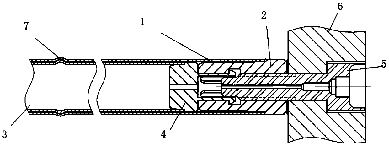
[0030] Such as figure 1 As shown, the connection structure of some embodiments of the present invention is composed of a conduit 1 , a conduit end plug 2 , a buffer tube 3 , a buffer tube end plug 4 , a screw 5 , and a lower tube seat 6 .

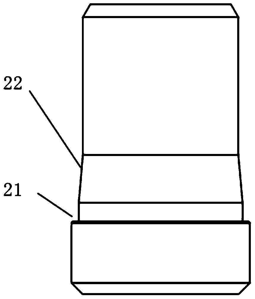
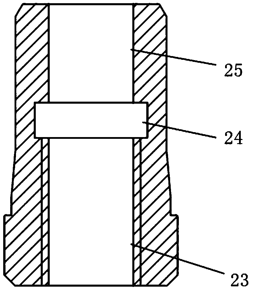
[0031] The catheter 1 is a straight pipe with an inner diameter of about 10mm-12mm and an outer diameter of about 11mm-14mm. The catheter end plug 2 is in the shape of a short rod with a length of about 16 mm to 25 mm. The outer surface is designed with a first step 21 for matching with the conduit 1, and the conduit 1 can be connected with the conduit end plug 2 by welding. At the same time, the first transition section 22 is designed with an angle of about 3-10° and a length of about 2-5 mm. The first transition section 22 facilitates the insertion of the catheter 1 into the catheter end plug 2 . The conduit end plug 2 has a hole in the center, and a threaded connection section 23 is designed at the lower end, which can be an M5 or M6 ...


PUM


Abstract

The invention discloses a novel automatic-positioning pipe-sleeved-pipe connection structure and an assembling method thereof. According to the structure, by cooperating an elastic buckle on an end plug of a buffer pipe with a slot on an end plug of a guide pipe, the buffer pipe can be automatically positioned in the guide pipe when being inserted into the guide pipe, and then shrinkage of the elastic buckle is limited by a screw, so that limiting of the elastic buckle on the end plug of the buffer pipe is realized, the buffer-pipe end plug is prevented from being out of the guide-pipe end plug, and finally the expanded connection between the guide pipe and the buffer pipe prevents the relative rotation of the guide pipe and the buffer pipe. The structure realizes automatic positioning of the buffer pipe in the guide pipe, the assembling operation is simplified, and production efficiency is improved.

Description

technical field [0001] The invention relates to the field of connection structure design of pressurized water nuclear reactor fuel assemblies, in particular to a connection structure between an outer tube and an inner tube. Background technique [0002] The pressurized water reactor fuel assembly consists of upper and lower nozzles, grids, fuel pipes, conduits, etc. Wherein, the conduit is connected to the upper and lower nozzles by mechanical connection or welding, and the conduit is connected to the grid by mechanical connection or welding. These connections determine the axial positioning of the nozzle and the grid in the fuel assembly. The fuel tubes are inserted into the grid and held in place by the grid. The above components make up the fuel assembly. [0003] In order to realize the controllability of fuel reaction in pressurized water reactor, it is necessary to control through the insertion of control rods into the fuel assembly. The control rod impacts the fuel...

Claims


Application Information

Patent Timeline
Patent Type & Authority Patents(China)
IPC IPC(8): G21C3/334
CPCY02E30/30
Inventor 何广进党宇刘松曾奇峰卢俊强
Owner SHANGHAI NUCLEAR ENG RES & DESIGN INST CO LTD
Learn More