Imaging device for electromagnetic radiation

An imaging device and electromagnetic ray technology, applied in the field of roentgen and/or gamma rays, can solve unsolved problems, and achieve the effects of small conversion layer thickness, high ray sensitivity, and high interaction probability

Inactive Publication Date: 2016-01-27
SIEMENS AG
View PDF7 Cites 4 Cited by
  • Summary
  • Abstract
  • Description
  • Claims
  • Application Information

AI Technical Summary

Problems solved by technology

However, this device still does not

Method used


Image

  • Imaging device for electromagnetic radiation
  • Imaging device for electromagnetic radiation
  • Imaging device for electromagnetic radiation

Examples


Embodiment Construction

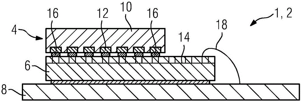
[0039] exist figure 1 A cross-section through an electromagnetic radiation imaging device 1 , which is here configured as a Roentgen detector 2 of a conventional device, is shown in a cross-sectional illustration. The Roentgen detector 2 includes a detection element 4 , a reading circuit board 6 and a basic circuit board 8 . Wherein, the detection element 4 is basically formed by the conversion layer 10, which is made of a semiconductor material such as CdTe or CdZnTe. Reader circuit board 6 is designed as an ASIC. On the side opposite to the readout circuit board 6 the detection element 4 has individual contact pins 12 which are each in contact with the readout electronics 14 arranged on the readout circuit board 6 via first solder contacts 16 . Readout electronics 14 , for example configured as CMOS arranged on the base body of an ASIC, is in contact with base circuit board 8 via wire connections 18 .

[0040] The incident roentgen rays now generate electron-hole pairs i...


PUM


Abstract

An imaging device (1) for electromagnetic radiation, especially for x-ray and/or gamma radiation, is disclosed. In an embodiment, the imaging device includes a layering including a number of detection elements (4), a number of read-out boards (6) and a base board (8). Each of the detection elements (4) is electrically contacted with a respective read-out board (6) via a plurality of first solder contacts (16). The or each read-out board (6) includes a plurality of through-contacts (20) and is electrically contacted with the base board (8) via a plurality of second solder contacts (24).

Description

technical field [0001] The invention relates to an imaging device for electromagnetic radiation, in particular for Roentgen and / or gamma radiation, wherein the device comprises a certain number of detection elements, a certain number of readout circuit boards and basic circuit boards. Background technique [0002] In the field of Roentgen diagnostic devices in medical technology, the development of high-resolution radiation detectors is of great importance for the detection capabilities of imaging medical devices and, in connection therewith, finally also for the possibility of diagnosis. [0003] Here, while having the advantage of a high spatial resolution capability, a good resolution for different radiation energies is also desirable for many medical applications, for example to be able to acquire different tissue structures whose absorption The power depends on the energy spectrum of the incoming radiation. In order to use the lowest possible radiation dose to the pati...

Claims


Application Information

Patent Timeline
IPC IPC(8): H01L27/146
CPCA61B6/4241H01L27/14661
Inventor L·丹泽M·拉巴延德因扎J·弗里吉
Owner SIEMENS AG
Why Eureka
Try Eureka