Supercharge Your Innovation With Domain-Expert AI Agents!

Magnetic resistance element and electronic device

A technology of resistive elements and electronic devices, applied in the direction of magnetic field-controlled resistors, etc., can solve the problems of low magnetic sensitivity, difficulty in using large magnetic field sensing arrays, and low mobility of carriers, and achieve the effect of high magnetic sensitivity.

Active Publication Date: 2017-11-28
AU OPTRONICS CORP
View PDF1 Cites 0 Cited by
  • Summary
  • Abstract
  • Description
  • Claims
  • Application Information

AI Technical Summary

Problems solved by technology

[0004] However, the magneto-resistor part is formed on an insulator, and the magneto-resistor part is amorphous or polycrystalline. Therefore, in general, the mobility of carriers is lower than that of a magneto-resistor part formed on a single crystal semiconductor substrate. Low, so the magnetic sensitivity is low
On the other hand, the magneto-resistor part is formed on a single crystal semiconductor substrate, and the size of the single crystal semiconductor substrate is limited, so it is difficult to be used in a large magnetic field sensor array

Method used


Image

  • Magnetic resistance element and electronic device
  • Magnetic resistance element and electronic device
  • Magnetic resistance element and electronic device

Examples


Embodiment Construction

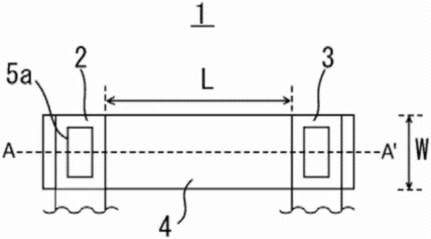
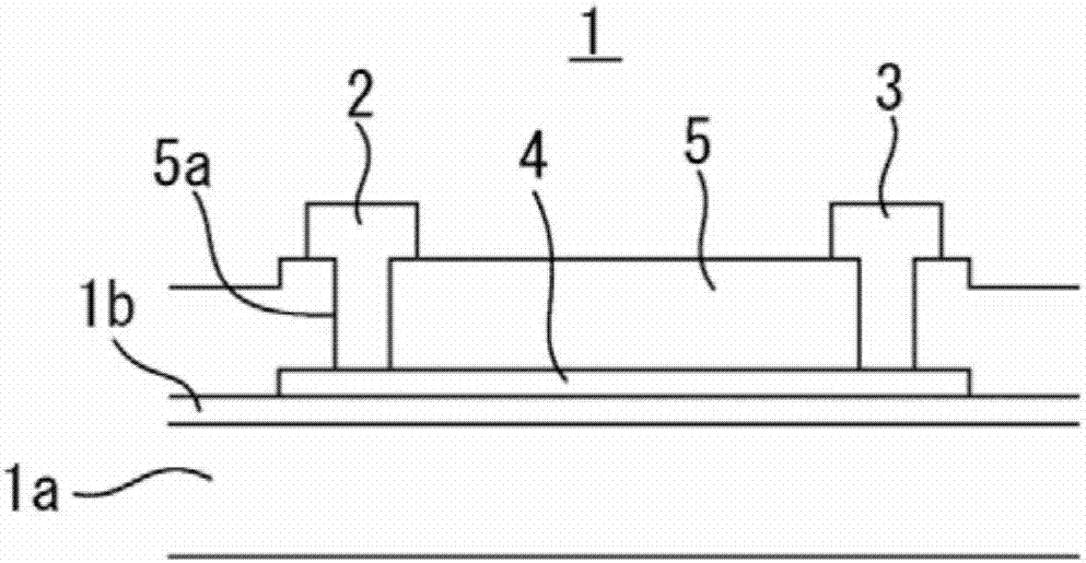
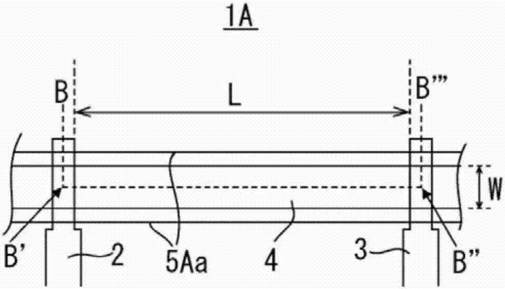
[0044] Hereinafter, embodiments of the present invention will be described with reference to the drawings. The magneto-resistive element 1 according to the embodiment of the present invention, as shown in FIG. The inductive resistance layer 4 , the magneto-inductive resistance layer 4 flows a current after a voltage is applied between the first electrode 2 and the second electrode 3 , and the resistance value changes according to the intensity of the magnetic field. The magnetoresistive layer 4 is formed by patterning an amorphous indium gallium zinc oxide (IGZO) thin film. In addition, patterning is to form a film into a desired shape, usually by etching, but the method is not limited.

[0045] Amorphous IGZO is composed of In, Ga, Zn and oxygen elements, and is an amorphous oxide with semiconductor properties. When this amorphous IGZO is used for the magnetoresistive layer 4, the magnetic sensitivity of the magnetoresistive element 1 can be improved even if the magnetoresi...


PUM


Abstract

A magneto-resistive element and an electronic device, the magneto-resistive element includes a first electrode, a second electrode, and a magneto-resistive layer. After applying a voltage and flowing a current between the first electrode and the second electrode, the resistance value of the magnetoresistive layer changes according to the intensity of the magnetic field. The magnetoresistive layer is formed by patterning an amorphous InGaZn thin film. The invention forms a magneto-inductive resistance layer on an insulating substrate or an insulating film, and has high magnetic sensitivity.

Description

technical field [0001] The present invention relates to a magnetoresistive element with a magnetoresistive layer formed on an insulating substrate (or an insulating film), and an electronic device using the magnetoresistive element. Background technique [0002] The resistance value of the magnetoresistive element changes according to the strength of the magnetic field. This phenomenon is called the magnetoresistance effect (MR Effect). Magneto-resistance effect, such as Figure 13A , Figure 13B As shown, in the magneto-resistive element MR, when the current i flows from the first electrode E1 to the second electrode E2 through the magneto-resistor part R, the carriers in the magneto-resistor part R are affected by the Lorentz force of the magnetic field and conduct electricity. The path is bent, thereby increasing the resistance value. In order to improve the magnetic sensitivity (the ratio of the resistance value change to the change of the magnetic field intensity), t...

Claims


Application Information

Patent Timeline
Patent Type & Authority Patents(China)
IPC IPC(8): H01L43/08H10N50/10
Inventor 小泽德郎郭志彻青木幸司木村睦松本贵明宫村祥吾
Owner AU OPTRONICS CORP
Features
  • R&D
  • Intellectual Property
  • Life Sciences
  • Materials
  • Tech Scout
  • Unparalleled Data Quality
  • Higher Quality Content
  • 60% Fewer Hallucinations
Learn More