
A low-voltage transformer area electric energy quality control device

A technology for power quality and low-voltage station areas, applied in the direction of reducing multi-phase network asymmetry, eliminating/reducing multi-phase network asymmetry, etc., and can solve problems such as three-phase imbalance, insulation layer damage, and excessive operating rate difference , to achieve the effect of improving the three-phase balance

Inactive Publication Date: 2016-01-27
STATE GRID CORP OF CHINA +3
View PDF6 Cites 0 Cited by
  • Summary
  • Abstract
  • Description
  • Claims
  • Application Information

AI Technical Summary

Problems solved by technology

Due to the existence of inductive loads, there is a phase difference between the current and voltage in the regional distribution network, thereby generating reactive power, resulting in a low power factor
In addition, it also causes another type of problem in the distribution network, that is, the three-phase unbalance problem
The reason is that the traditional three-phase four-wire distribution transformers are mostly connected in the regional distribution network, and the transformer capacity is less than 100kVA, accounting for about 50% of the global transformers, and these small-capacity transformers are vulnerable to seasonal single-phase loads. (such as single-phase tea frying machines, etc.), which in turn causes low-voltage single-phase loads in the distribution network to be unable to be fully distributed manually, the actual operating rate of the distributed loads differs too much, and the uncontrollable capacity increase of single-phase users is inevitable. Three-phase unbalance problem caused by low-voltage distribution network
[0003] This unbalanced three-phase load will inevitably lead to an increase in the neutral wire current. Since it is equal in magnitude and opposite in direction, superposition on the neutral wire will cause neutral wire overload, overheating, and electromagnetic interference, affecting the supply voltage waveform, insulation Layer damage, lower power factor, lower service life of transformers and electrical equipment, etc., will ultimately seriously affect the regional voltage qualification rate index

Method used


Image

  • A low-voltage transformer area electric energy quality control device
  • A low-voltage transformer area electric energy quality control device
  • A low-voltage transformer area electric energy quality control device

Examples


specific Embodiment approach

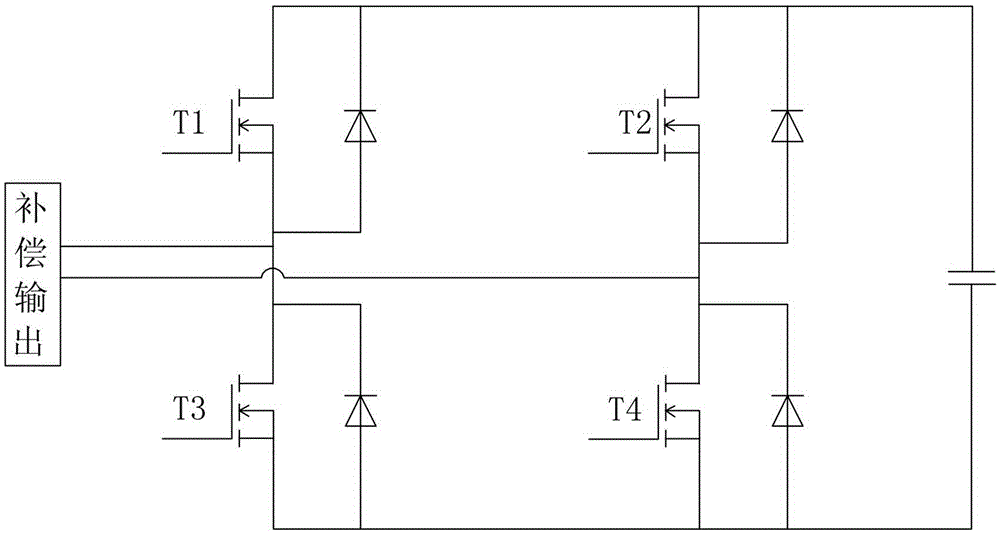
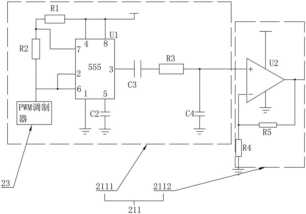
[0026] As an improved specific implementation, the inverter 21 includes a triangular wave generating circuit 211, a first MOS transistor T1, a second MOS transistor T2, a third MOS transistor T3, and a fourth MOS transistor (T4). The drain of a MOS transistor (T1) is coupled to the drain of the second MOS transistor T2, the source of the first MOS transistor T1 is coupled to the drain of the third MOS transistor T3, and the third MOS transistor T1 The source of the second MOS transistor T4 is coupled to the source of the fourth MOS transistor T4, the source of the second MOS transistor T2 is coupled to the drain of the fourth MOS transistor T4, the source of the first MOS transistor T1 is coupled to the third MOS transistor T1 The node between the drains of the MOS transistor T3 extends out of the first output end, and the node between the source of the second MOS transistor T2 and the drain of the fourth MOS transistor T4 extends out of the second output end, so A Schottky di...


PUM


Abstract

The invention provides a low-voltage transformer area electric energy quality control device comprising a transformer and a control loop. The transformer is a ZigZag transformer. The control loop comprises an inverter, a sampling circuit, a PWM modulator, a protection circuit and a filter. With the transformer and the control loop, zero-sequence current of external lines can be effectively detected and can be timely compensated for effectively to filter zero-sequence current.

Description

technical field [0001] The invention relates to a device for controlling electric energy, more specifically, relates to a device for controlling the quality of electric energy in a low-voltage station area. Background technique [0002] Over the past ten years, with the rapid development of power electronics technology, the number of high-power power electronic devices in the regional power distribution system has increased day by day, which has not only improved the efficiency and automation level of the regional industrial devices, but also brought about its power distribution system. Reactive problem. Due to the existence of inductive loads, there is a phase difference between the current and voltage in the regional distribution network, thereby generating reactive power and resulting in a low power factor. In addition, another type of problem is caused in the distribution network, that is, the three-phase unbalanced problem. The reason is that the traditional three-pha...

Claims


Application Information

Patent Timeline
IPC IPC(8): H02J3/26
CPCY02E40/50
Inventor 陈海宏郑贤舜夏陈喆奚洪磊郑晟金海晨夏惠惠
Owner STATE GRID CORP OF CHINA
Learn More