
Automatic power generating control method for wind farm

A technology of automatic power generation control and wind farm, applied in wind power generation, single grid parallel feeding arrangement, etc., can solve the problems of lack of dynamic adjustment, small active power command, loss of power generation, etc., to improve regulation and management level and increase active power loss The effect of compensation and improvement of power generation efficiency

Inactive Publication Date: 2016-01-27
NR ELECTRIC CO LTD +1
View PDF2 Cites 1 Cited by
  • Summary
  • Abstract
  • Description
  • Claims
  • Application Information

AI Technical Summary

Problems solved by technology

[0006] Failure to consider the actual power generation capacity of wind turbines: the distribution is based on a fixed ratio, and the actual power generation capacity of each wind group cannot be taken into account. It is easy to cause a mismatch between the actual power generation capacity and the active power command, that is, the active power command allocated to the wind group that can generate more power is small and cannot The active power command distributed by the wind turbine group for power generation is large, which is easy to cause the loss of the overall power generation
[0007] Lack of dynamic adjustment: When there is a large deviation between the actual active power issued by the wind group and the distributed active power command, since the active power command distributed by each wind group remains unchanged, it is lost to compensate for the power generation deviation by adjusting other wind groups with adjustment capabilities In the end, the scheduling control requirements cannot be met, which reduces the control and management level of the wind farm by the grid dispatcher and the wind power utilization rate of the wind farm.

Method used


Image

  • Automatic power generating control method for wind farm

Examples


Embodiment Construction

[0018] Attached below figure 1 The specific implementation manners of the present invention will be further described.

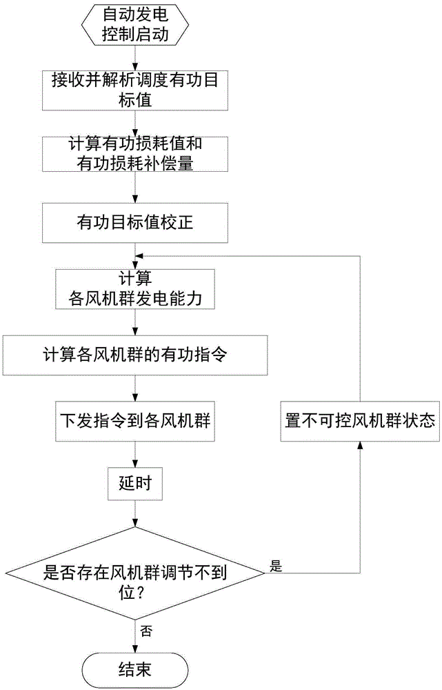
[0019] Firstly, the active power target value is corrected for the active power loss situation, and the new active power target value is obtained by adding the active power loss compensation amount correction on the basis of the active power target value issued by dispatching; secondly, the active power distribution calculation and the order are carried out in combination with the actual power generation capacity of each wind group distribution calculation based on the corrected new active power target value, and the actual power generation capacity of each wind group is fully considered in the distribution process, the active power command of each wind group is obtained and the active power command is issued to each wind group; finally, according to the execution situation Dynamically adjust the control command and track the execution of each fan group. If ...


PUM


Abstract

The invention discloses an automatic power generating control method for a wind farm. Firstly, the method considers active loss situations and corrects an active target value issued by a scheduler. Secondly, the method considers the practical power generating capability of each fan group and carries out active distribution calculation and instruction issuing, so that the practical power generating capability of each fan group is taken into consideration fully during distribution, and active instructions of each fan group are obtained and set to the fan group. Finally, a control instruction is dynamically adjusted according to execution situations, and the execution situation of each fan group is tracked. If fan group power adjustment is not enough, distribution calculation is conducted again according to the adjustment capability of each fan group. The active instructions of each fan group are dynamically adjusted, so that the fan groups capable of adjustment undertakes extra power adjustment tasks. The method effectively increases the power generating benefits of the wind farm, improves the regulating management level of the wind farm by a power grid scheduler, and improves the wind power generating utilization rate.

Description

technical field [0001] The invention relates to the field of automatic control of electric power systems, in particular to the automatic control technology of wind farms. Background technique [0002] At present, more and more wind farms are being built in China. Faced with the pressure of large-scale wind power access to the grid, automatic power generation control of wind farms is an effective measure to increase the rate of wind power grid integration. [0003] The current automatic power generation control scheme commonly used in wind farms is to allocate and calculate the active power target value issued by dispatching according to a fixed ratio (for example, according to the installed capacity ratio of each wind group), and obtain the active power command of each wind group and send it to each wind group. The monitoring system of each wind turbine group specifically regulates the power generation output of each wind turbine group. The active power command of each fan ...

Claims


Application Information

Patent Timeline
Patent Type & Authority Applications(China)
IPC IPC(8): H02J3/48
CPCY02E10/76
Inventor 王小平金岩磊葛立青徐浩黄伟翟剑华
Owner NR ELECTRIC CO LTD
Learn More