Electric motor

A technology of motors and rotors, applied in the field of motors, can solve problems such as huge investment, and achieve the effect of uniform heat transfer

Active Publication Date: 2016-01-27
SIEMENS AG
View PDF6 Cites 3 Cited by
  • Summary
  • Abstract
  • Description
  • Claims
  • Application Information

AI Technical Summary

Problems solved by technology

However, this cooling concept only allows the integration of the internal cooling circuit with great investment

Method used


Image

  • Electric motor
  • Electric motor
  • Electric motor

Examples


Embodiment Construction

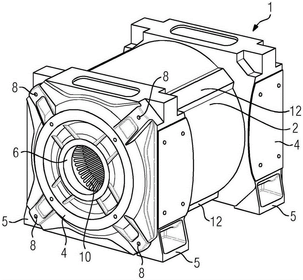
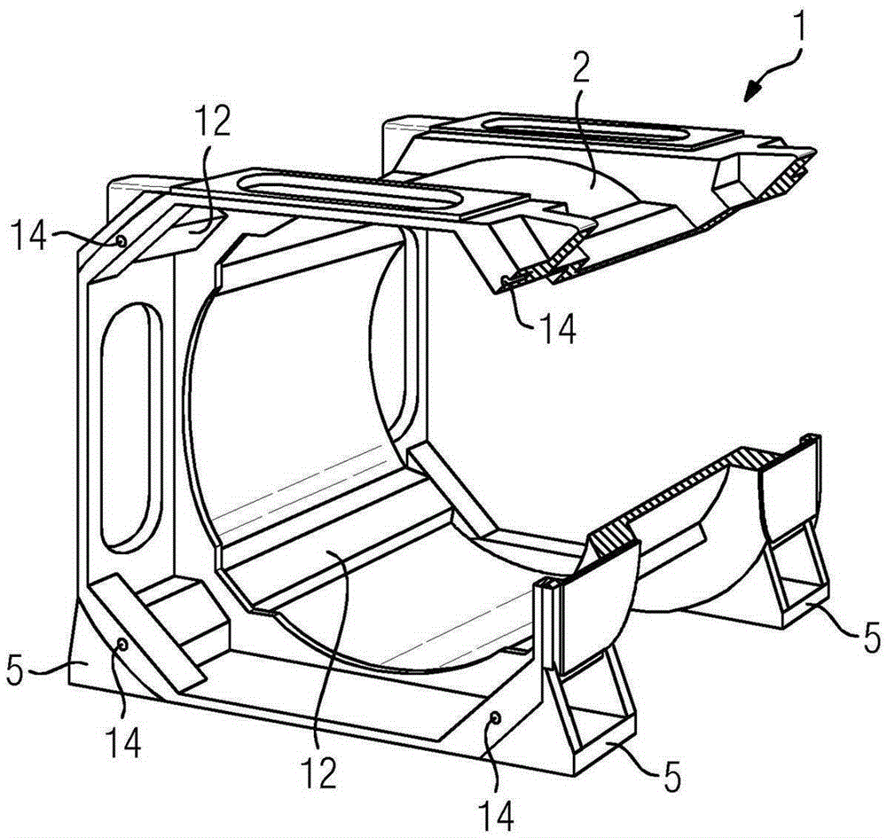
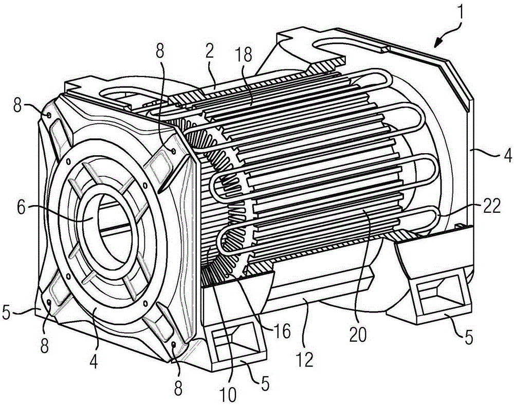
[0029] figure 1 The housing 1 for the electric motor is shown in plan view. The housing 1 is produced as a cast part, but can alternatively also be produced from steel. It comprises a single-walled housing 2 which is designed essentially in the shape of a cylindrical circumference. At the axial ends of the cylinder are arranged bearing caps 4 which form the top and bottom faces of the cylinder. In the axial edge region, the housing 2 merges into a square in order to secure the end shield 4 . In this case, the side lengths of the square axial end regions in cross section exceed the circumference of the cylinder of the housing.

[0030] In this case, the side surfaces of the axial end regions form the mounting edge, on which the housing stands. For this purpose, four feet 5 are additionally provided on the bottom in the region of the two-sided edges. The endshield 4 includes a central, circular opening 6 for supporting the not shown rotor of the electric motor. In the regi...


PUM


Abstract

The problem addressed by the invention is that of providing an electric motor having a stator, a rotor, and a cooling circuit for the rotor, comprising a substantially cylindrical-shell-shaped casing (2), which permits an especially technically simple integration of an inner cooling circuit for the rotor. To solve this problem, an outwardly directed cavity (12), which extends in an axial direction with respect to the cylinder, is introduced into the casing (2) and a hollow-cylinder-shaped laminated stator core (10) is arranged inside the housing (1), said stator core having grooves (18) arranged on the outside. The cooling lines (22) are arranged in the grooves (18), and the laminated stator core (10) has recesses (20), which are arranged on the outside and extend in an axial direction and which are part of a cooling circuit for the rotor.

Description

technical field [0001] The invention relates to an electric motor with a stator, a rotor and a cooling circuit for the rotor, comprising a housing with a substantially cylindrical peripheral casing, wherein, relative to the cylinder, the , the recess oriented towards the outside is inserted into the housing. Background technique [0002] The electric motor functions to generate mechanical energy, usually rotational kinetic energy, from electricity. In an electric motor, the force exerted by a magnetic field on a conductor through which an electric current flows through a coil is converted into motion. For this purpose, the electric machine comprises a stationary stator and a rotor rotating therein, which is mounted in corresponding bearings. In this case, the coil windings can be arranged either on the rotor or—in electric motors with integrated permanent magnets—on the stator. [0003] Highly utilized electric motors, especially those of the latter type of construction, ...

Claims


Application Information

Patent Timeline
Patent Type & Authority Applications(China)
IPC IPC(8): H02K1/20H02K5/20
CPCH02K1/20H02K5/203H02K9/19
Inventor 托马斯·科克赖纳·格里勒恩贝格尔
Owner SIEMENS AG
Why Eureka
Try Eureka