Gas-liquid distributing device applied to packing partition-plate rectifying tower

A gas-liquid distribution and gas distribution technology, applied in the direction of fractionation, can solve the problems of small gas and liquid two-phase flow area, high requirements for internal components of the tower, uneven distribution of rising gas and falling liquid, etc., to improve the uniformity of gas. The degree of distribution, the effect of increasing the effective flow area, and facilitating installation and maintenance

Inactive Publication Date: 2016-02-03
天津盛丰源机械设备有限公司
View PDF0 Cites 0 Cited by
  • Summary
  • Abstract
  • Description
  • Claims
  • Application Information

AI Technical Summary

Problems solved by technology

However, due to the introduction of partitions, the internal structure of the rectification tower has become more complicated, and the requirements for the internal components of the tower are relatively high, especially the gas and liquid distributors on both sides of the partitions in the tower, the rising gas at the bottom of the tower, the tower The distribution uniformity of the top-down liquid through the gas and liquid distributor directly affects the gas and liquid mass transfer efficiency in the tower, and at the same time has an important influence on the product purity and energy consumption in the rectification process.
[0003] At present, the gas and liquid distribution devices widely used in ordinary rectification towers usually cannot meet the needs of clapboard rectification towers in terms of structure. The small two-phase flow area and the uneven distribution of ascending gas and descending liquid hinder the development of high-efficiency gas distributors used in baffle distillation columns, which is also one of the reasons that restrict the wide application of baffle distillation towers.

Method used


Image

  • Gas-liquid distributing device applied to packing partition-plate rectifying tower
  • Gas-liquid distributing device applied to packing partition-plate rectifying tower

Examples


Embodiment Construction

[0023] The gas-liquid distribution device of the present invention will be further described in detail in conjunction with the accompanying drawings:

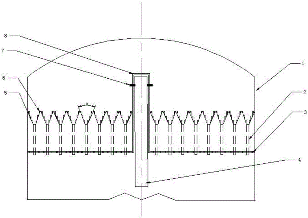
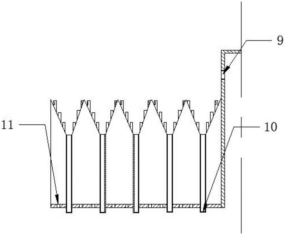
[0024] like figure 1 , 2 As shown, in the new gas-liquid distribution device applied to both sides of the partition 4 in the partition rectification tower 1, the left and right are symmetrical structures, with a convex fixed structure 8 in the middle, and a V-shaped gas with round holes of different apertures. Distribution structure 5 and strip liquid distribution structure 2. The gas-liquid distribution device includes a V-shaped gas distribution structure 5 , a liquid distribution structure 2 , a convex fixed structure 8 , and a bottom plate 3 .

[0025] The V-shaped gas distribution structure 5 is installed on both sides of the partition 4 of the partition rectification tower 1, and is the upper structure of the gas-liquid distribution device, including a V-plate and a gas distribution cap 6 . The V plate is a metal steel...


PUM


Abstract

The invention relates to a gas-liquid distributing device applied to a packing partition-plate rectifying tower. The gas-liquid distributing device comprises a V-shaped gas distribution structure, a liquid distribution structure, an inverted-T-shaped fixing structure and a bottom plate. The V-shaped gas distribution structure is composed of gas distribution structure V plates and gas distribution caps and made of metal steel plate materials. Rising gas is evenly distributed on the two sides of a partition plate through the gas distribution caps of the V-shaped gas distribution structure. The liquid distribution structure is formed by evenly-arranged liquid falling troughs, falling liquid passes through liquid-falling circular holes in the liquid falling troughs to be distributed to the lower end of the device in a linear mode, and even distribution of the liquid is achieved. The inverted-T-shaped fixing structure is located at the right-upper end of the partition plate to achieve the effect of fixing the partition plate. The bottom plate is a semicircular steel plate provided with evenly-arranged square holes and evenly-arranged gas inlet holes, and the rising gas enters the device through the gas inlet holes in the bottom plate. By means of the gas-liquid distributing device, gas and liquid on the two sides of the partition plate are effectively distributed, and the partition plate in the center of the partition-plate rectifying tower is effectively fixed; meanwhile, wall flow in the partition-plate rectifying tower is effectively reduced, and installation and maintenance are convenient.

Description

technical field [0001] The invention relates to a gas-liquid distribution device used in a clapboard rectification tower, in particular to a novel gas-liquid distribution device. Background technique [0002] As a new type of thermally coupled rectification column, the clapboard rectification column realizes the separation of multiple components in a single column by installing vertical clapboards in the conventional rectification column, which has the huge advantages of low energy consumption and low cost. Compared with conventional distillation towers, partitioned rectification towers can reduce energy consumption and investment by about 30%, and for some special system separations, energy savings can reach 50%-60%. However, due to the introduction of partitions, the internal structure of the rectification tower has become more complicated, and the requirements for the internal components of the tower are relatively high, especially the gas and liquid distributors on both ...

Claims


Application Information

Patent Timeline
Patent Type & Authority Applications(China)
IPC IPC(8): B01D3/14B01D3/32
Inventor 王娜
Owner 天津盛丰源机械设备有限公司
Why Eureka
Try Eureka