
A soil column leaching device

A technology of leaching and soil column, which is applied in the direction of measuring device, sampling device, soil material testing, etc., can solve problems such as easy wall flow, long time consumption, and soil column collapse, so as to eliminate pressure difference, reduce time, and reduce wall The effect of the flow phenomenon

Active Publication Date: 2019-05-21
张豫 +1
View PDF7 Cites 0 Cited by
  • Summary
  • Abstract
  • Description
  • Claims
  • Application Information

AI Technical Summary

Problems solved by technology

Most of the current vertical soil columns are one-piece soil columns, which are prone to wall flow during soil column leaching experiments, and soil column collapses are prone to occur during the sampling process; when the diameter of the vertical soil column is large, the soil column The leaching experiment takes a long time

Method used


Image

  • A soil column leaching device
  • A soil column leaching device
  • A soil column leaching device

Examples


Embodiment 1

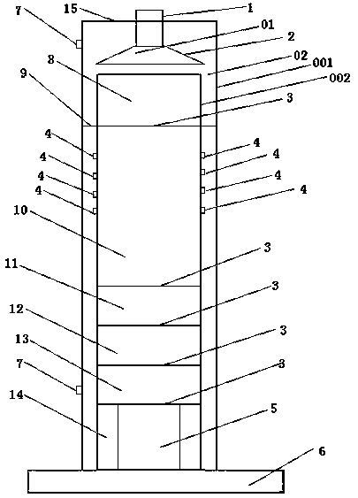
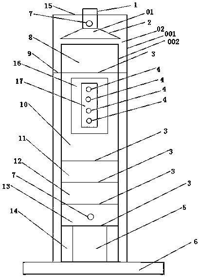
[0030] A soil column leaching device according to the present invention includes a support base 6, a leaching pipe 02, and a water distributor 01. The leaching pipe 02 is placed on the support base 6 and the leaching pipe 02 and the support base 6 pass through Threaded connection, the water distributor 01 is connected to the top of the leaching pipe 02; the leaching pipe 02 is composed of an inner pipe 002 and an outer pipe 001, and the inner pipe 002 is placed inside the outer pipe 001; The inner pipe 002 of the leaching pipe 02 is divided into a buffer layer 8, a soil layer 10, a fine quartz sand layer 11, a nylon mesh layer 12, a coarse quartz sand layer 13, and a filtrate collection layer 14 from top to bottom. The layers are separated by at least one layer of filter screen, and the bottom of the inner pipe 002 of the leaching pipe is sealed; the inner pipe soil layer 10 is provided with a plurality of sampling ports 4; the nylon mesh of the inner pipe Between the layer 12...

Embodiment 2

[0040] Embodiment 2 Atmospheric pressure experiment

[0041] The present invention is further described in conjunction with embodiment 1:

[0042]According to the needs of the experiment, soil at different depths in the farmland was collected, and a soil column leaching device described in Example 1 was used to conduct a soil column leaching experiment to measure the content and distribution of organic pollutants in the soil. Open the sealing plate 15, close all sampling ports 4, fill the test with coarse quartz sand layer, nylon mesh layer, fine quartz sand layer and soil layer from bottom to top to the inner pipe 002 of the leaching pipe and between adjacent layers and layers respectively Separate and compact through at least 1 layer of strainer. After the column loading is completed, first install the sealing plate 15 on the outer tube 001 of the leaching tube, connect the dry tube 1 of the water distributor 01 with the sealing plate 15 on the top of the outer tube 001 of ...


PUM

PropertyMeasurementUnit
radiusaaaaaaaaaa
thicknessaaaaaaaaaa
radiusaaaaaaaaaa

Abstract

A soil column leach device includes a support base, a leach pipe, and a water distributor. The leach pipe is placed on the support base, and the leach pipe and the support base are connected through threads. The water distributor is connected to the top of the leach pipe; The leach tube is composed of an inner tube and an outer tube, and the inner tube is placed inside the outer tube. The outer pipe of the leach pipe is divided into two upper and lower parts that are not connected to each other. When the air inlet on the upper part of the outer pipe of the leach pipe is connected to the pump, the pressure of the inner pipe of the leach pipe of the soil column leach device can be increased according to the experimental needs. , thereby effectively reducing the time required to perform soil column leach experiments; a soil column leach device of the present invention can be used to sample the soil layer while pressurizing the inner tube of the leach pipe of the soil column leach device. The air inlet at the lower part of the outer tube is connected to the pump, which increases the pressure outside the soil layer sampling port, which can effectively reduce or even eliminate the pressure difference between the inside and outside of the sampling port. At this time, sampling through the sampling window can reduce the phenomenon of wall flow and The occurrence of soil column collapse.

Description

technical field [0001] The invention relates to a soil column leaching device. Background technique [0002] In recent years, the problem of soil pollution in my country has become increasingly prominent, posing a serious threat to the ecological environment, food safety and human health. [0003] The pollution of heavy metals and organic pollutants in the soil-plant-groundwater system is particularly prominent and increasingly serious. by [0004] Take soil heavy metal pollution as an example. At present, there are about 150 million mu of polluted arable land in China. [0005] The food amounted to 12 million tons, causing direct economic losses of more than 20 billion yuan. According to the environmental protection monitoring system of the Ministry of Agriculture in 2000 [0006] The survey of 82.23 million mu of soil in 329 seriously polluted areas in 24 provinces and cities in China found that the area of ​​farmland agricultural products polluted exceeding the standa...

Claims


Application Information

Patent Timeline
Patent Type & Authority Patents(China)
IPC IPC(8): G01N33/24G01N1/16
CPCG01N1/16G01N33/24G01N33/245
Inventor 张豫朱拥军石荣媛蔡德所李英田
Owner 张豫
Learn More