Bubbler

A bubbler and bubbling technology, which is applied in the field of gas bubblers and cylinder bubbling devices, can solve the problems of poor distribution uniformity and small gas holdup, achieve length reduction, increase gas-liquid contact amount, and benefit fully The effect of the contact reaction

Inactive Publication Date: 2016-02-03
天津隆雷科技有限公司
View PDF0 Cites 3 Cited by
  • Summary
  • Abstract
  • Description
  • Claims
  • Application Information

AI Technical Summary

Problems solved by technology

The existing gas distributor has the disadvantages of small gas holdup and poor distribution uniformity

Method used


Image

  • Bubbler
  • Bubbler

Examples


Embodiment Construction

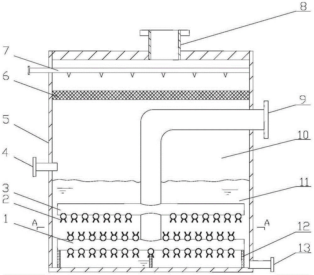
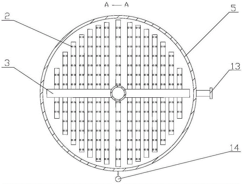
[0018] The present invention will be further described below in conjunction with the accompanying drawings. Such as figure 1 As shown, the upper part of the cylinder body 5 is a purified gas chamber 10, and the lower part is an absorption liquid chamber 11. In the purified gas chamber 10, a mist eliminator 6 for removing the purified gas water mist is installed, and the connection with the cylinder body is a detachable bolt Connect, there are several spray pipes 7 for cleaning the mist eliminator on it, and several shower nozzles are provided. The inlet pipe 9 used for exhaust gas entry is welded on the cylinder wall, and one end extends into the cylinder body and is vertically connected and communicated with the primary air distribution pipe 1 . The first-level gas distribution pipe 2, multiple secondary gas distribution pipes 1 and injection pipes 2 parallel to each other form a disc gas distributor, and the outlets of all injection pipes 2 are located on the same horizonta...


PUM


Abstract

The invention relates to a bubbler. The bubbler is composed of a barrel body, a gas inlet pipe, a first-stage gas distribution pipe, a second-stage gas distribution pipe, a jetting pipe, an exhaust port, a liquid desulfurizer inlet, a slag liquid discharging port and the like. An absorbing liquid cavity is formed in the lower portion of the barrel body, and a purifying gas cavity is formed in the upper portion of the barrel body. The gas inlet pipe is connected with the barrel wall in a welding mode, one end of the gas inlet pipe is perpendicularly welded to the first-stage gas distribution pipe and communicated with the first-stage gas distribution pipe. The first-stage gas distribution pipe and the second-stage gas distribution pipe form two disk type gas distributor devices which are arranged in an up-and-down mode. The jetting pipe is welded to the second-stage gas distribution pipe, and the jetting pipe and the second-stage gas distribution pipe are welded in an inverted-V shape on the same cross section. The exhaust pipe port is welded to an end cover of the barrel body. The liquid desulfurizer inlet is located at the 1 / 2 position of the total height of the barrel body. The slag liquid discharging port is located on the bottommost portion of the barrel body. The bubbler can substantially increase the total area of a gas outlet, the waste gas treatment amount is large, desulfurizing efficiency is improved, the structure is compact and reasonable, and installation is convenient.

Description

technical field [0001] The invention relates to a gas bubbler, in particular to a method for removing SO 2 , SO 3 The utility model relates to a barrel bubbling device for acidic gas, which belongs to the field of waste gas treatment equipment. technical background [0002] Bubbler, also known as bubbling reactor, is a gas-liquid mass transfer or reaction device. Its function is to use the gas transported by the flue gas pipeline to contact and react with the lye in the device to remove SO in the flue gas. 2 , SO 3 and other acidic gases to achieve the purpose of desulfurization and gas purification. With the rapid development of my country's energy industry and the construction of large-scale coal-fired power plants, fuel consumption continues to increase, SO 2 The amount of emissions is increasing, and the air pollution caused is becoming more and more serious. Therefore, the construction of desulfurization devices is an indispensable control measure. At present, the ...

Claims


Application Information

Patent Timeline
Patent Type & Authority Applications(China)
IPC IPC(8): B01D53/78B01D53/50
Inventor 王娜
Owner 天津隆雷科技有限公司
Why Eureka
Try Eureka