
Oil injection equipment and oil injection process for engine cylinder sleeves

A technology for engine cylinders and cylinder liners, which is applied in the direction of injection devices, liquid injection devices, and devices for coating liquid on the surface, etc., which can solve the problems of inconvenient control and low fuel injection efficiency, and achieve high fuel injection efficiency, convenient control, and High volume effects

Inactive Publication Date: 2016-02-03
ZYNP GRP ANHUI CO LTD
View PDF5 Cites 1 Cited by
  • Summary
  • Abstract
  • Description
  • Claims
  • Application Information

AI Technical Summary

Problems solved by technology

At present, after the cylinder liner is formed, it needs to be sprayed on its surface, but the existing equipment for cylinder liner oil injection has the defects of low oil injection efficiency and inconvenient control

Method used


Image

  • Oil injection equipment and oil injection process for engine cylinder sleeves

Examples


Embodiment Construction

[0014] Below in conjunction with specific embodiment the invention is described in further detail.

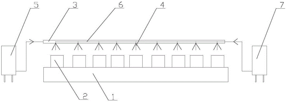
[0015] see figure 1 , a fuel injection device for engine cylinder liners, comprising a cylinder liner placement platform 1, cylinder liners 2 are placed vertically on the cylinder liner placement platform 1 in turn, and oil pipes are arranged on the cylinder liner placement platform 1 3. The lower part of the oil pipe 3 is connected with the fuel injection nozzle 4, and the fuel injection nozzle 4 is arranged on the top of each cylinder liner 2 one by one. The air guide pipe 6 communicates with each fuel injector 4 for providing air pressure for fuel injection of the fuel injector 4 , and one end of the air guide pipe 6 is connected to the air compressor 7 .

[0016] When in use, the oil flows into the oil pipe from the oil barrel 5 and gathers at the fuel injection nozzle 4. At this time, the air compressor 7 is turned on, the air guide pipe takes in air, and the fuel injecti...


PUM


Abstract

The invention provides oil injection equipment and oil injection process for engine cylinder sleeves. The oil injection equipment comprises a cylinder sleeve containing table. The cylinder sleeves are sequentially and vertically placed on the cylinder sleeve containing table. An oil pipe is arranged on the cylinder sleeve containing table. The lower portion of the oil pipe is connected with oil injection nozzles through pipelines. The oil injection nozzles are arranged at the top ends of the cylinder sleeves in a one-to-one correspondence manner. One end of the oil pipe is connected to an oil drum. An air guide pipe is further arranged in the oil pipe, communicated with the oil injection nozzles, and used for providing air pressure for oil injection of the oil injection nozzles. One end of the air guide pipe is connected to an air compressor. The oil injection process includes the steps such as control over the flow of the oil injection nozzles. A pneumatic system is used for automatic oil injection on the cylinder sleeves, and the oil injection equipment and the oil injection process have the beneficial effects of being high in oil injection efficiency, convenient to control and large in handling capacity.

Description

technical field [0001] The invention relates to the technical field of cylinder liner manufacturing, in particular to an oil injection device and an oil injection process for an engine cylinder liner. Background technique [0002] At present, due to the shortage of oil resources and environmental pollution, it is increasingly important to improve the fuel efficiency of automobile engines and reduce exhaust emissions. The two major components of an automobile engine are the piston and the cylinder liner. Among them, the cylinder liner requires its material to have properties such as high temperature resistance, wear resistance, pressure resistance, and light weight. The improvement of engine performance will inevitably put forward higher requirements on the processing of cylinder liners. At present, after the cylinder liner is formed, it needs to be sprayed on its surface, but the existing equipment for cylinder liner oil injection has the defects of low oil injection effici...

Claims


Application Information

Patent Timeline
Patent Type & Authority Applications(China)
IPC IPC(8): B05B13/02B05B9/04B05D1/02
CPCB05B13/0278B05B9/04B05D1/02
Inventor 黄德松杨俊朱斌
Owner ZYNP GRP ANHUI CO LTD
Learn More