

Slide door of machine tool
A technology for sliding doors and machine tools, which is applied to door/window accessories, power control mechanisms, wing leaf control mechanisms, etc. It can solve the problems of large loads of metal wires, wear and damage of metal wires, achieve high-speed opening and closing, and reduce useless The effect of space and compact configuration setting space
- Summary
- Abstract
- Description
- Claims
- Application Information
AI Technical Summary
Problems solved by technology
Method used
Image

Examples
no. 1 approach 〉
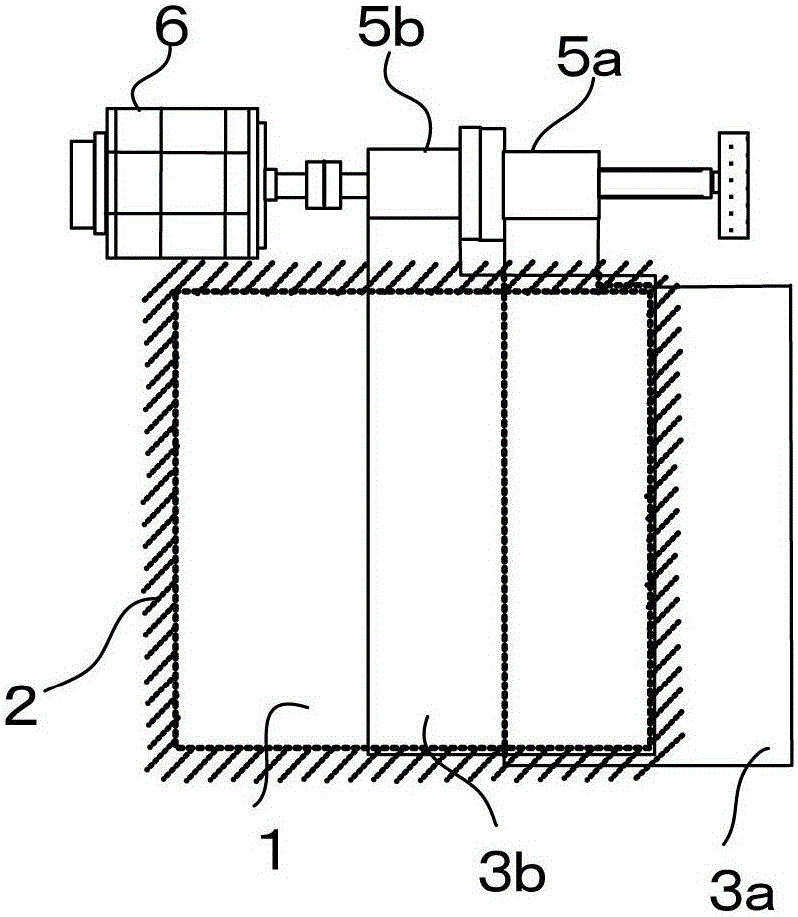
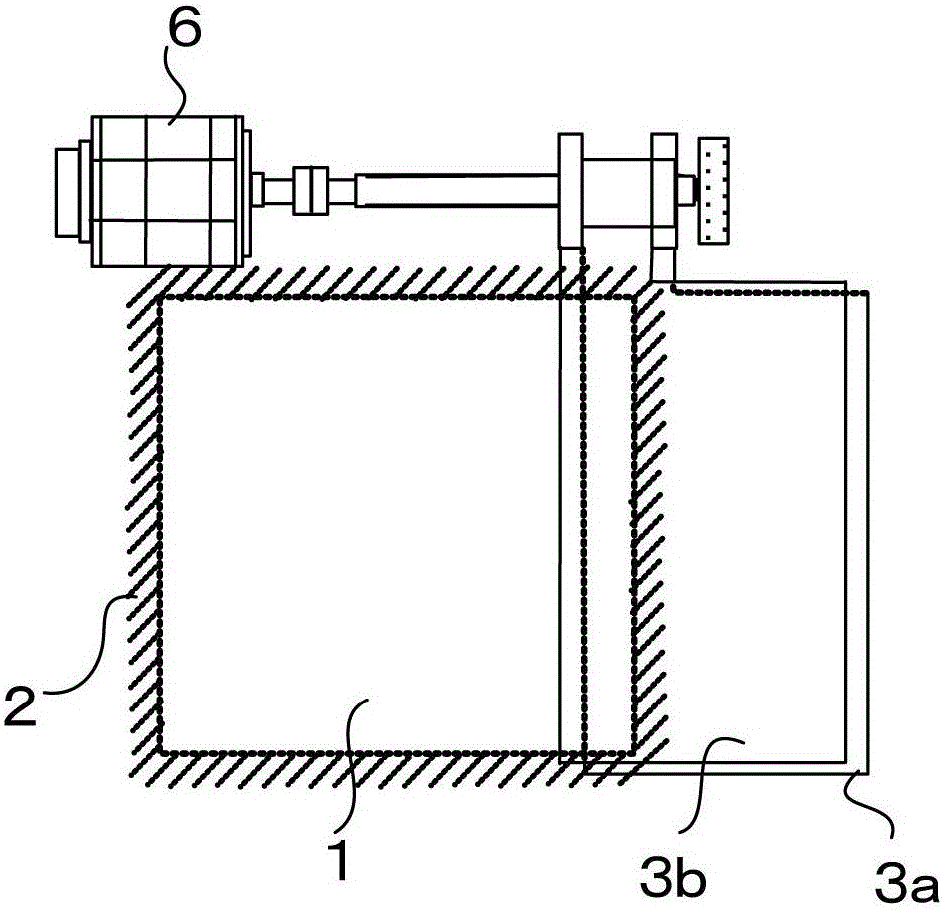
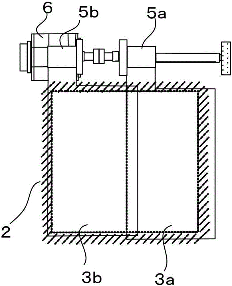
[0026] Figure 1A , Figure 1B , Figure 1C , Figure 1D It is a schematic diagram of the first embodiment of the present invention. Figure 1A , Figure 1B , Figure 1C is the main view, Figure 1A Indicates the state where the opening is opened halfway, Figure 1B Indicates the state where the opening is fully opened, Figure 1C Indicates the state where the opening is closed. in addition, Figure 1D is a top view.
[0027] A machining space where a workpiece is cut with a tool is covered by a fixed cover 2, and a first door 3a and a second door 3b for opening and closing an opening 1 provided in the fixed cover 2 are provided. On the upper part of the first door 3a and the second door 3b, a first ball screw 4a and a second ball screw 4b are arranged in parallel, and the first ball screw 4a and the second ball screw 4b are respectively screwed together. There are a first nut 5a and a second nut 5b. The extension member 7a of the first door 3a is fixed to the first n...
no. 2 approach 〉
[0040] Figure 4 It is a schematic diagram of the second embodiment.
[0041] In this second embodiment, instead of providing a power transmission mechanism, a driving motor is provided for each ball screw, and the rest is the same as that of the first embodiment.
[0042] The motor shaft 8a of the first motor 6a is connected to the first ball screw 4a so that the axis center is aligned with the shaft coupling 10a, and the second motor shaft 8a is connected to the second ball screw 4b so that the shaft center is aligned with the shaft coupling 10b. 6b motor shaft 8b. The rest of the structure is the same as that of the first embodiment except that the power transmission mechanism 9 is not provided, so description thereof will be omitted.
[0043] The first door 3a is driven by the first motor 6a via the first ball screw 4a and the first nut 5a. The second door 3b is driven by the second motor 6b via the second ball screw 4b and the second nut 5b. The first door 3a and the ...
no. 3 approach 〉
[0046] In the first to second embodiments described above, the two doors are moved in the same direction to open and close the opening, but in this third embodiment, the two doors are moved in opposite directions to open and close the opening.
[0047] Figure 5A , Figure 5B is a schematic diagram of the first form of the third embodiment, Figure 5A is a top view, Figure 5B is the main view. The first ball screw 4 a is coupled to the motor shaft of the motor 6 through a coupling 10 so as to coincide with the shaft center of the motor. In addition, the first ball screw 4 a and the second ball screw 4 b are connected via a power transmission mechanism 9 . The extension member 7a of the first door 3a is fixed to the first nut 5a screwed to the first ball screw 4a. In addition, the extension member 7b of the second door 3b is fixed to the second nut 5b screwed to the second ball screw 4b. Figure 5A , Figure 5B A state in which the opening is closed by two doors, the fi...
PUM
 Abstract
Description
Claims
Application Information